background image

16 


Door Installation


10 

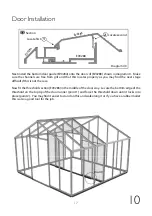
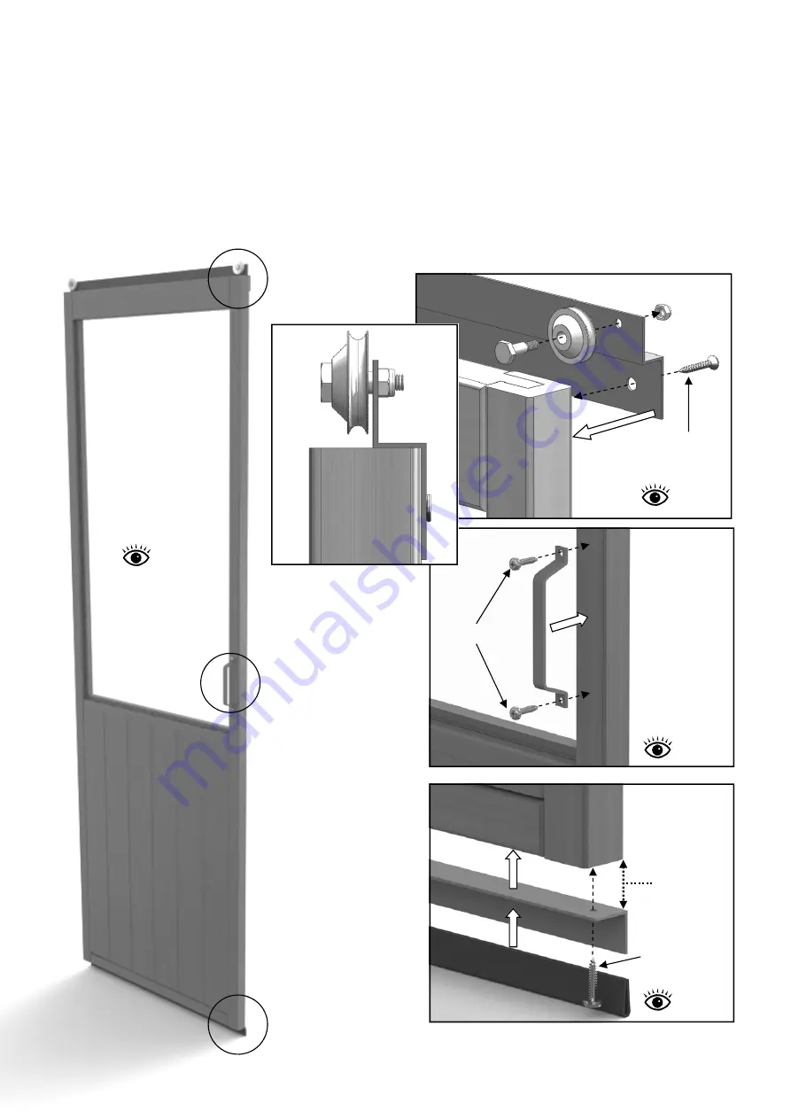
Before installing the door you need to fit the running gear.  Start by assembling the door wheels 
onto the door top bracket, diagram 37.   Once assembled fit the bracket to the top of the door using 
15mm countersunk screws.  
Now fit the door handle with 25mm round head screws, diagram 38. 
Slide the door glide onto the door guide bracket and then fix to the bottom of the door.  Keep the 
down leg of the guide in line with the inside edge of the door, diagram 39.  

Dia. 37 

Dia. 38 

Dia. 39 

Diagram 38 

Diagram 39 

558 

x  

1031 

EV0320 

EV0324 

25mm Screw 

25mm Screw 

EV0290 

Keep in 

line 

External 

External 

External 

Fit one 
handle on 
the left of 
one of your 
doors and 
one on the 
right. 

Diagram 37 

EV0318M


25mm Screw 

External 

Summary of Contents for EVOLUTION EIGHT

Page 1: ...06 13...

Page 2: ...2 12 Wide Evolution Cedar Partition Assembly Instructions Contents Introduction Base Preparation Side Assembly Glazing Door Installation Frame Finishing Section 1 2 3 4 5 Page 3 4 5 6 7 8 9 10 14...

Page 3: ...ther vulnerable locations To minimise the risk of wind damage try to select as sheltered a site as possible e g beside a hedgerow or garden fence Additional Considerations Please bear in mind that ass...

Page 4: ...crete You should also wear suitable gloves when handling the glass this also helps to keep it clean It is good practice to pre load the bar capping with screws and position this around the greenhouse...

Page 5: ...stall the aluminium base section Line the 2 base sections up with the side glazing bars as shown below Fit a base bracket to the end that intersects the side base Use a crop head bolt to fit the brack...

Page 6: ...lazing bars Start by drilling pilot holes in the cill section through the mortise holes diagram 3 Also drill 2 holes in the top of the gable glazing bars through the lap joint These should be 25 30mm...

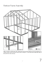
Page 7: ...Base EV0061 Internal When in position with the base flush with the end of the cill in the doorway circled in diagram 5 fix with two 25mm screws at the two points shown in diagram 5 Keep this section s...

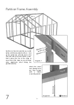
Page 8: ...of bars Line up the gable bars with the slots in the roof bars and secure with 40mm screws Don t secure this bar to the ridge or eaves bar at this stage as you will need some adjustment when fitting t...

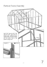
Page 9: ...xt fit the opposite side to the aluminium base again with two 25mm screws With this section supported insert the door header into the mortise holes in the gable bars diagram 9 Dia 9 Dia 9 Diagram 9 EV...

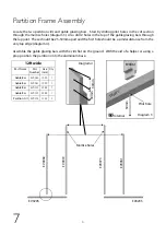
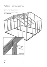
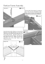
Page 10: ...Partition Frame Assembly 7 With the door header in place fit the other partition roof bar Again secure this with 40mm screws to the gable bars at the lap joint EV0201 EV0073 Diagram 10 40mm Screw Dia...

Page 11: ...ion you may have to lift the roof bar to do this and also adjust the position of the base joining bracket Once in position make sure it is running parallel with the side glazing bar and fix with 40mm...

Page 12: ...idge This shows the best angle for the screw Again you want to be careful the end of the screw doesn t come through at any point 80mm Screw 5 0 m m S c r e w EV0024 EV0201 Keep a tight fit EV0201 EV00...

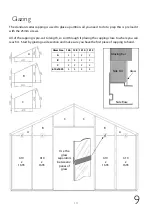
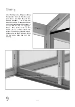
Page 13: ...ws All of the capping is pre cut to length so sort through it placing the capping close to where you can reach it Start by glazing a side section and make sure you have the first piece of capping to h...

Page 14: ...side capping to start with fitting this close to the aluminium base you may wish to adjust this once the roof capping is fitted Then do the same for the middle sections and the other side section Onc...

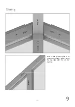
Page 15: ...15 9 Glazing Cdr capping top edge Once all the partition glass is in place you can finally secure it along the top edge with the roof bar capping EV0218 EV0222 EV0218 EV0228 EV0217 Ridge Bar...

Page 16: ...ndle with 25mm round head screws diagram 38 Slide the door glide onto the door guide bracket and then fix to the bottom of the door Keep the down leg of the guide in line with the inside edge of the d...

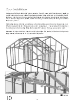
Page 17: ...s not the case Now fit the threshold section EV0286 in the middle of the door way Locate the bottom edge of the threshold on the top lip of the door runner point 1 and force the threshold down until i...

Page 18: ...same time you need to locate the door guide with the door runner point 7 Holding the door up form the runner below so that it is just located in the runner diagram 42 point 7 fix the track with the fi...

Page 19: ...py with the position of your track and the door is running freely fix the middle screw to the track point 3 Finally attach the vertical supports to each end with a 10mm nut and bolt diagram 43 Using a...

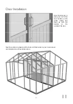
Page 20: ...should be fitted as close to the door as possible while still allowing it to pass by freely Dia 45 You can now install the rebate strips to the inside of your door Pilot hole the strips first It is b...

Page 21: ...n is glazed and the doors are fitted return to your main manual and complete the roof assembly section Once the strips are in place you can fit the door handles on the inside simply line these up with...

Page 22: ...Alton Greenhouses TGP Ltd Blythe Park Cresswell Stoke on Trent ST11 9RD Telephone 01782 385 409 www Altongreenhouses co uk sales altongreenhouses co uk...

Reviews: