23
Lantern Assembly
9
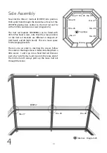
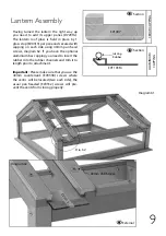
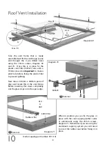
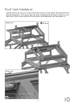
Now that the main frame has been assembled you can
begin to construct the lantern top which once assembled
will be lifted on whole.
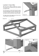
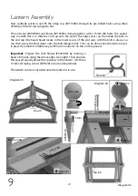
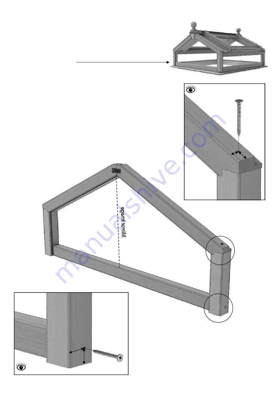
Begin lantern assembly by constructing its gable ends. Drill
accurately placed pilot holes first (diagrams 50– 52), note
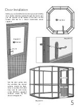
these screw heads will be visible externally. Use 50mm CSK
screws to fix through the handed (EV1094 / EV1095)
lantern side corner mortices to pick up the cill section
(EV1089).
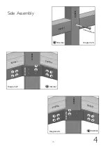
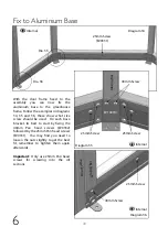
Again making sure that the pilot holts are accurately
positioned use 50mm CSK screws down through the
handed lantern top gable bars (EV1092 / EV1093) into the
side corners (diagram 51) .
X 2
EV108
9
E
V
1
0
9
4
E
V
1
0
9
5
EV
10
92
EV
10
93
Diagram 50
Diagram 51
Diagram 52
50mm Scr
ew
50mm Scre
w
22mm
28m
m
16
m
m
15m
m
M
ir
ro
r
Im
a
g
e
Dia. 51
Dia. 52
External
External
Summary of Contents for Evolution octagonal
Page 1: ...1 04 19...

