10
Dia. 5
Dia. 6
EV0057
Dia. 7
Rear Assembly
5
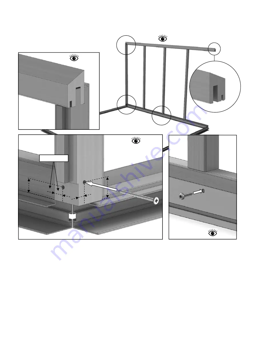
To install this section you will need a helper to hold the side in position or strap it to a set of steps.
Drill two pilot holes in the bottom of the side corner bar as in diagram 6. The height of these holes
should be about 15mm on the side face and 25mm on the rear face measured from the end of the
bar, try to keep these at different heights to each other so the screws don’t intersect each other.
Now offer the side corner to the eaves bar slotting the tennon into the mortise shown in diagram 5,
do not fix this joint as it will be done at a later stage. Screw the bottom of the corner glazing bar to
the end of the cill (80mm screw) making sure the rebate for the glass lines up with the front face of
the side cill (diagram 6).
Once the side corner bar is in place this will give you the correct position on the aluminium base and
you can fix the base to the side cill with 25mm screws (diagram 7).
Diagram 5
Diagram 6
80mm Sc
rew
Keep faces in line
EV0057
EV0057
16mm
16mm
Side
Face
Rear
Face
15mm
25mm
Diagram 7
25m
m Sc
rew
Eaves Ba
r
Side Cill
Side Cill
Side Bas
e
EV0030
External
External
Internal
(Outside
Edge)
Internal


