18
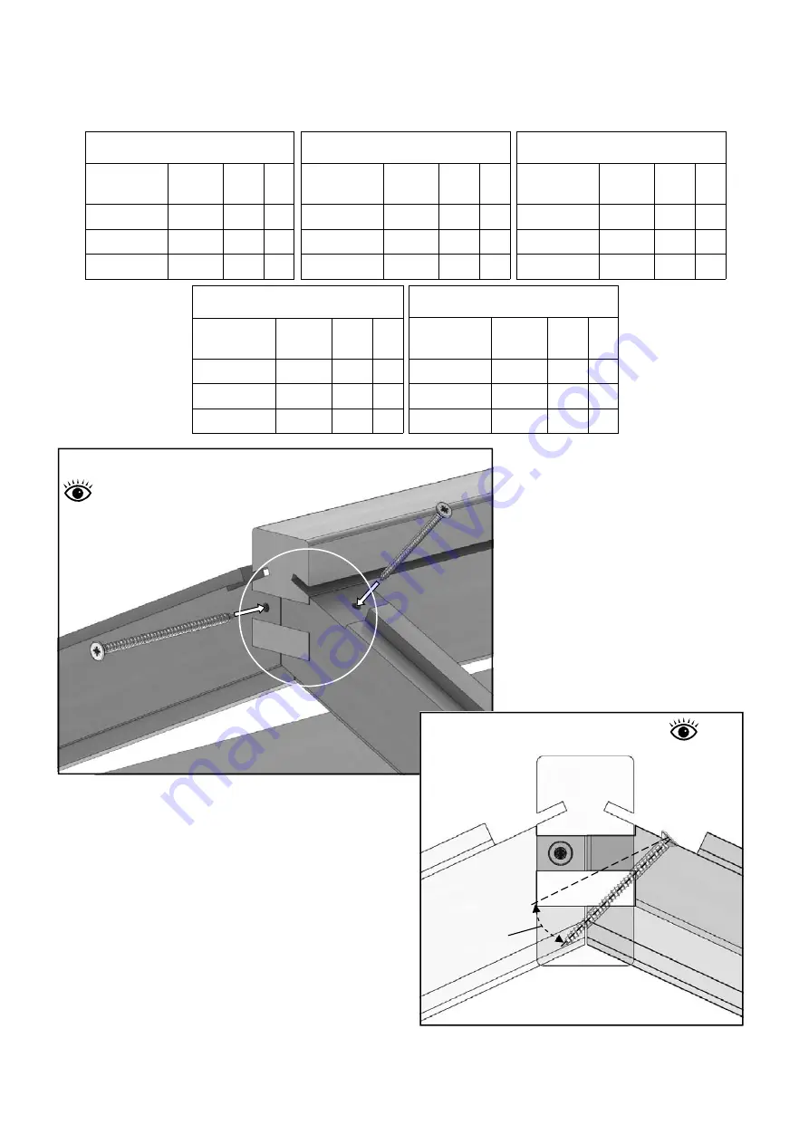
With help locate the ridge with the roof corner
bars. Once into position, drill 2 pilot holes into
each end as in diagram 19. Try to keep the angle
something close to diagram 20, through the top
face of the roof corner bars. This is to prevent
the end or the screw coming through the
bottom of the roof glazing bar. This angle will
also give a much better and stronger fixing.
Roof Assembly
7
Diagram 20
Dia. 17
80m
m Scr
ew
50
m
m
S
cre
w
Optimum
screw angle
EV00
44
EV
004
5
6ft
Part Name
Part
Number
Size
(mm)
Qty
Ridge
EV0026 1934 1
Glazing Bar
EV0035 2151 4
Eaves Spacer
EV0024 586 6
4ft
Part Name
Part
Number
Size
(mm)
Qty
Eaves Spacer
EV0024 586 4
Ridge
EV0025 1304 1
Glazing Bar
EV0035 2151 2
8ft
Part Name
Part
Number
Size
(mm)
Qty
Ridge
EV0027 2564 1
Glazing Bar
EV0035 2151 6
Eaves Spacer
EV0024 586 8
10ft
Part Name
Part
Number
Size
(mm)
Qty
Ridge
EV0028 3194 1
Glazing Bar
EV0035 2151 8
Eaves Spacer
EV0024 586 10
12ft
Part Name
Part
Number
Size
(mm)
Qty
Ridge
EV0029 3824 1
Glazing Bar
EV0035 2151 10
Eaves Spacer
EV0024 586 12
Ridge
External
Diagram 19
X-ray
example


