background image


- 4 - 

HubWayEX16SP Active Unit

12

34

CH 1-4

CH 5-

8

28

VA

C

OF

F

24

VA

C

+ DA

TA

 --

1-

8

+ DA

TA

 --

9-16

56

78

91

01

11

2

CH 9-12

28

VA

C

OF

F

24

VA

C

13

14

15

16

CH 13-1

6

AC POWER

16

15

14

13

12

11

10

98

76

54

32

1

OFF

RESET

12

34

CH 1-4

CH 5-

8

28

VA

C

OF

F

24

VA

C

+ DA

TA

 --

1-

8

56

78

AC POWER

87

65

43

21

OFF

RESET

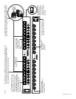
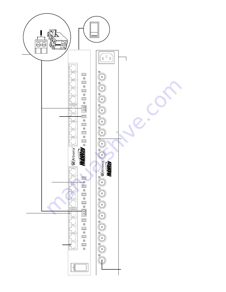
1a - Channels 1-16:

 CAT-5 or

higher structured cable to Video /Balun Combiners at cameras 1-16. When using an optional  HubSat4D/Di any of the outputs  can be utilized for the data transmission to PTZ’s.

1f - BNC Connector:


Video outputs to head end equipment (DVR).

1d - Output voltage  switches:

 Selects 

24VAC/28VAC/ OFF for each output.

1b - Channels 1-4, Channels 5-8, Channels 9-12 & Channels 13-16: CAT-5 or higher structured cable from optional HubSat4D enables  video transmission from up to four (4) cameras.

1g - LED(s) 1-16:


Video signal indicators.

1h - IEC 320 Connector:  Grounded line cord included.

Fig. 1

1e - Data:

 Removable terminal blocks for RS422/RS485 

input from head end equipment (DVR) for PTZ control.

+    --

Data input fr

om

Head End Equipment (DVR).

To

p View


1i - Input Voltage  Switch:

 Selects 

115VAC

/230VAC  

(switch is located  on the left side of  the unit).

115V

AC       220V

AC

1c - LED(s) 1-16:


Power indicators.

Front

Rear

Summary of Contents for HubWayEX16SP

Page 1: ...UTP Transceiver Hub with Integral Isolated Camera Power Installation Guide HubWayEX16SP UL Listed sixteen 16 Channel Active UTP Transceiver Hub with Integral Isolated Camera Power More than just power TM Video Data Power ...

Page 2: ...ctor of the HubWayEX16SP For US Canada the plug end is a 3 prong type B plug used for standard 115VAC receptacles as provided with unit Fig 1h pg 4 For non North American 230VAC applications use the appropriate 3 prong plug that matches the local standard receptacle 6 Set voltage output selector switch of each camera channel for 24VAC or 28VAC Fig 1d pg 4 7 Connect the BNC video outputs for HubWay...

Page 3: ...ras Figs 3a 3b pg 5 Polarity must be observed 13 Connect the terminals marked DATA of the HubWayAv or HubWayDv Video Balun Combiners to the data terminals of the cameras for PTZ control Figs 2a 2d pg 5 Polarity must be observed When using fixed cameras disregard this step 14 Connect the BNC connector of the HubWayAv or HubWayDv Video Balun Combiners to the BNC video outputs of the cameras Figs 3a ...

Page 4: ... PTZ s 1f BNC Connector Video outputs to head end equipment DVR 1d Output voltage switches Selects 24VAC 28VAC OFF for each output 1b Channels 1 4 Channels 5 8 Channels 9 12 Channels 13 16 CAT 5 or higher structured cable from optional HubSat4D enables video transmission from up to four 4 cameras 1g LED s 1 16 Video signal indicators 1h IEC 320 Connector Grounded line cord included Fig 1 1e Data R...

Page 5: ...DC cameras Red Based on camera load and structured cable length 1 White Orange VIDEO 2 Orange VIDEO 3 White Green DATA 4 Blue AC 1 5 White Blue AC 2 6 Green DATA 7 White Brown AC 2 8 Brown AC 1 Fig 4 CAT 5 Structured Cable Wiring Color Codes and PIN Configurations Video Power Video Data Power Data Video Head End Equipment DVR RS485 HubWayAv HubWayAv Fixed Camera Fixed Camera Max video 5000 ft PTZ ...

Page 6: ...Camera Four 4 Video signals on a single CAT 5 Data CAT 5 HubWayDv HubWayDv Video Data 12VDC PTZ Camera Power Video Data Power Video Data Power 24VAC 28VAC Camera Power Provided by HubSat4D Di 115VAC Input 50 60Hz Video Power CAT 5 CAT 5 CAT 5 12VDC Fixed Camera HubWayAv 24VAC Fixed Camera Video Coax Four 4 Video signals on a single CAT 5 Power 24VAC Fixed Camera HubWayDv HubWayDv Video 12VDC Fixed...

Page 7: ...ct s enclosure that may be of sufficient magnitude to constitute an electric shock The exclamation point within an equilateral triangle is intended to alert the user to the presence of important operating and maintenance servicing instructions in the literature accompanying the appliance CAUTION To reduce the risk of electric shock do not open enclosure There are no user serviceable parts inside R...

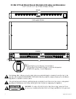
Page 8: ...when installing the unit vertically Rack Mount Installation 1 Remove and discard factory installed screws from both sides of rack chassis Fig 7a 2 Install mounting brackets A on the left and right side of rack chassis using the four 4 flat head screws B included Fig 7b 3 Place unit into desired EIA 19 rack position and secure with mounting screws not included Fig 7c Fig 9 Fig 8 Shelf Installation ...

Reviews: