background image


TroveHN 

- 5 - 

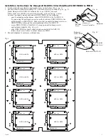
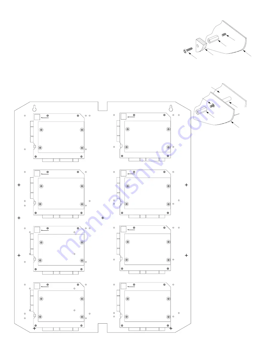
Installation Instructions for Honeywell NetAXS-123 with/without NXD1/NXD2 to THN2:

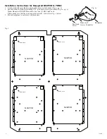
1.   Fasten standoffs (provided) to appropriate pems on backplane (Fig. 4, pg. 5).
2.   Mount boards to standoffs utilizing 5/16” pan head screws (provided) (Fig. 4a, pg. 5).

  Note: Honeywell NetAXS-123 modules have one (1) RJ45 jack each. 

    Please make sure that they are mounted correctly, as shown in Fig. 4 below. 
    In order to properly mount and connect NXD1/NXD2 do the following:
      -  prior to mounting on backplane, attach NXD1/NXD2 to the NetAXS-123 
        by connecting the multi-pin connector on the bottom of NXD1/NXD2 to the
        multi-pin jack on NetAXS-123. Make sure that pre-installed bump screws on 
        NXD1/NXD2 go through the corresponding holes in NetAXS-123.
      -  secure NXD1/NXD2 to NetAXS-123 using pre-installed bump screws 
    and 

included 

standoffs 

(Fig. 4b, pg. 5).

      -  after NXD1/NXD2 is firmly attached and connected to NetAXS-123, 
        follow steps 1 and 2 above to mount them onto THN2.
3.   Mount backplane to enclosure with hardware.

Pem

Standoff

Honeywell

Access Controller

Backplane

Pan Head

Screw

Standoff

Bottom of NetAXS-123

Bottom of

NXD1/NXD2

Pre-installed

Bump Screw

Mounting

Hole

Fig. 4a

Fig. 4b

RJ45 Jack

RJ45 Jack

RJ45 Jack

RJ45 Jack

RJ45 Jack

RJ45 Jack

RJ45 Jack

RJ45 Jack

NetAXS-123

NetAXS-123

NetAXS-123

NetAXS-123

NetAXS-123

NetAXS-123

NetAXS-123

NetAXS-123

NXD1 or NXD2

NXD1 or NXD2

NXD1 or NXD2

NXD1 or NXD2

NXD1 or NXD2

NXD1 or NXD2

NXD1 or NXD2

NXD1 or NXD2

Fig. 4

Summary of Contents for THN2

Page 1: ...Installation Guide All registered trademarks are property of their respective owners More than just power Installing Company ______________________ Service Rep Name ___________________________________...

Page 2: ...accordance with the National Electrical Code NFPA 70 ANSI and with all local codes and authorities having jurisdiction Product is intended for indoor use only 1 Remove backplane from enclosure Do not...

Page 3: ...ws provided Fig 2a pg 3 3 Mount backplane to enclosure with hardware Access Controller Position Chart for the Following Models Altronix Board Pem Mounting Altronix Power Supply Charger or Sub Assembly...

Page 4: ...lizing 5 16 pan head screws provided Fig 3a pg 4 Note Honeywell NX4PCB modules have one 1 RJ45 jack each Please make sure that they are mounted correctly as shown in Fig 3 below 3 Mount backplane to e...

Page 5: ...3 Make sure that pre installed bump screws on NXD1 NXD2 go through the corresponding holes in NetAXS 123 secure NXD1 NXD2 to NetAXS 123 using pre installed bump screws and included standoffs Fig 4b pg...

Page 6: ...ppropriate pems on backplane Fig 5 pg 6 2 Mount boards to standoffs utilizing 5 16 pan head screws provided Fig 5a pg 6 3 Mount backplane to enclosure with hardware Pem Standoff Honeywell Access Contr...

Page 7: ...25 375 644 6mm 19 375 492 1mm 12 625 320 7mm 0 45 11 4mm 1 0 25 4mm 1 0 25 4mm 9 2 233 7mm 8 5 215 9mm 16 25 412 8mm 0 156 3 96mm 9 2 233 7mm 7 5 190 5mm 0 45 11 4mm THN2 Dimensions H x W x D 25 375...

Page 8: ...50 8mm 2 00 50 8mm 5 25 133 35mm 5 25 133 35mm 7 00 177 79mm 2 00 50 8mm 2 00 50 8mm 27 00 685 8mm 3 50 88 9mm 0 5625 14 29mm 2 415 61 34mm 0 685 17 399mm 1 77 44 96mm 3 50 88 9mm 21 50 546 1mm 19 80...

Reviews: