background image


Trove1DM1 / TDM1 / Trove2DM2 / TDM2 

- 3 - 

Standoff

Altronix

Sub-Assembly or 

DMP 734 plastic housing

Backplane

Pan Head

Screw

Pem

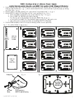
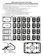
TDM1: Configuration of Altronix Power Supply

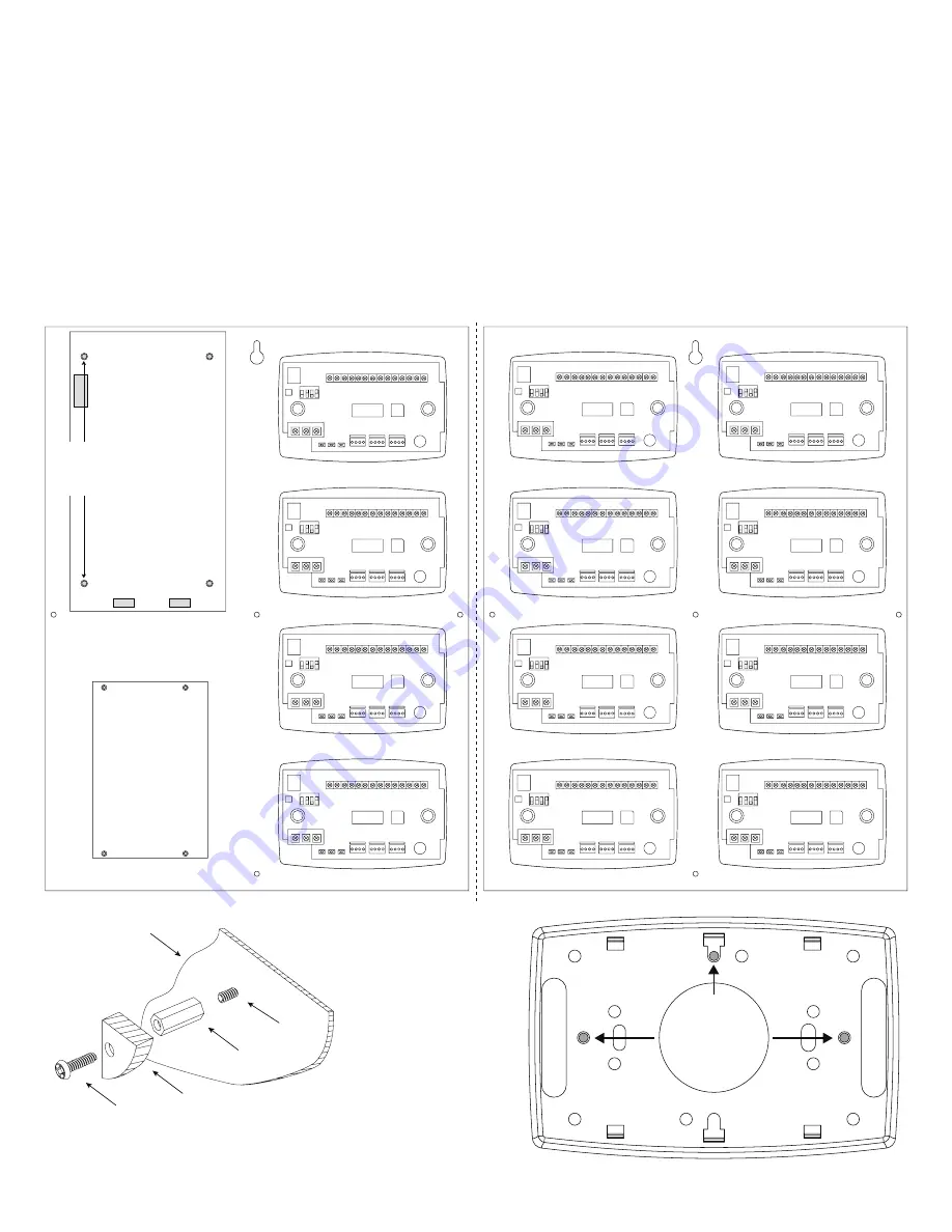
and/or Sub-Assembly Boards and DMP 734 and/or 734N Wiegand Modules

1.  Fasten standoffs (provided) to pems that match the hole pattern for Altronix Power Supply/Chargers or Altronix


Sub-Assembly boards (Fig. 2, pg. 3). Fasten metal standoffs in the correct locations to provide proper grounding, 


see below (Fig. 2, pg. 3).

2.  Mount boards to standoffs utilizing 5/16” pan head screws (provided) (Fig. 2, 2a, pg. 3).

3.  Mount DMP 734 and/or 734N modules into the correct positions (Fig. 2, pg. 3):


a.  fasten standoffs to appropriate pems on the backplane (Fig. 2, 2b, pg. 3).


b.  remove DMP 734 board from the plastic housing. 


Use the base part of the housing to mount onto TDM1 (Fig. 2b, pg. 3).


c.  secure the base of DMP 734 to the standoffs using provided 5/16” pan head screws.


d.  make all necessary connections before reassembling DMP 734 Wiegland.

4.  Fasten TDM1 backplane to Trove1 enclosure utilizing pan head screws (provided).

Altronix

Power

Supply

Metal

Standoff

Placement

Altronix

Sub-

Assembly

734

Interface

Module

734

Interface

Module

734

Interface

Module

734

Interface

Module

734

Interface

Module

734

Interface

Module

734

Interface

Module

734

Interface

Module

734

Interface

Module

734

Interface

Module

734

Interface

Module

734

Interface

Module

Mounting

Standoff

Placement

Fig. 2 - Trove1DM1/TDM1 Configurations

Fig. 2b

Fig. 2a

Summary of Contents for Trove2DM2

Page 1: ...TDM2 Altronix DMP backplane only Installation Guide All registered trademarks are property of their respective owners More than just power Installing Company ______________________ Service Rep Name _...

Page 2: ...lent in desired location opposite hinge Slide the tamper switch bracket onto the edge of the enclosure approximately 2 from the right side Fig 1 pg 1 Connect tamper switch wiring to the Access Control...

Page 3: ...2 pg 3 a fasten standoffs to appropriate pems on the backplane Fig 2 2b pg 3 b remove DMP 734 board from the plastic housing Use the base part of the housing to mount onto TDM1 Fig 2b pg 3 c secure th...

Page 4: ...h U1 RED WHT GRN BLK LC RA AS Z1 GND Z2 Z3 GND Z4 Z4 1 2 3 4 5 6 7 8 9 10 11 12 13 14 RED YEL GRN NO C NC Piezo KYPD OUT KYPD IN PROG RED RED J2 J4 J5 J1 J3 S1 ON RELAY ON WEIGAND READ LED DATA XMT LE...

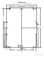
Page 5: ...Trove1DM1 TDM1 Trove2DM2 TDM2 5 TDM1 Dimensions 16 625 x 12 5 x 0 3125 422 3mm x 317 5mm x 7 9mm 6 25 158 75mm 16 625 422 3mm 15 65 397 5mm 12 5 317 5mm 8 15 207mm 0 5 12 7mm 0 5 12 7mm...

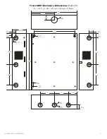
Page 6: ...375 x 19 375 x 0 325 644 5mm x 482 6mm x 8 3mm 7 5 190 5mm 25 375 644 5mm 19 375 482 6mm 7 5 190 5mm 24 95 633 7mm 12 62 320 6mm 12 62 320 6mm 8 5 215 8mm 0 45 11 4mm 1 0 25 4mm 1 0 25 4mm 16 245 412...

Page 7: ...mm 4 5 114 3mm 2 75 69 85mm 1 25 31 75mm 1 5 38 09mm 8 5 215 9mm 18 0 457 2mm 1 0958 27 83mm 0 6012 15 27mm 6 5 165 1mm 1 25 31 75mm 1 25 31 75mm 1 5 38 09mm 8 5 215 9mm 6 5 165 1mm 0 569 14 52mm 1 94...

Page 8: ...x D 27 25 x 21 75 x 6 5 692 2mm x 552 5mm x 165 1mm G 1 25 31 75mm 1 25 31 75mm 6 25 158 75mm 6 25 158 75mm 6 75 171 45mm 8 25 209 54mm 8 00 203 2mm 1 5 38 1mm 1 25 31 75mm 0 85 21 59mm 0 85 21 59mm 1...

Reviews: