background image

17


   Language: English  Model: Netti III HD  Version: February 2013

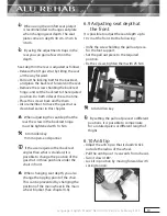
6.4 Front castors

To take of

• Press the release button under the front            

   fork.

To mount

• Lead the quick release axle into the 

   bearing house. Pull the fork slightly to

   ensure that the fork is fully locked.


Sand and sea water (salt used for 

        gritting in the winter) can damage the

        bearings of the front castors.  Clean the

        wheelchair thoroughly after exposure.

6.5 Seat height at the front

The seat height depends on:

• Size of front castors.

• Size of front fork.

• Check the angle of the castor bearing

   house.

In chapter 5 there is several models of

both front castors and front forks to

choose between.  For to change the 

front castors or front fork - unfix the

wheel and place it in the required 

position in the front fork.

Angle of bearing house

Correctly adjusted angle of the front fork is 

important to achieve proper manoeuvring 

qualities of the wheelchair. Unfix the two 

screws on the inside of the frame enough 

to adjust the the eccentric nuts. Angle the 

bearing house, so that it is  90° relative to the 

ground, tighten the screws with 16 Nm

1 pc 5 mm Allen key

The bearing house can not be adjusted  

       in height. 

Check the position of the anti tip.

6.6 Seat height at the rear

The seat height at the rear depends on:

• Size of main wheel.

• Position of main wheel.

Main wheel

Unfix the hub bushing, including washer and 

nut, and mount it in required position in the 

main wheel bracket.

2 pcs 24 mm open-end spanner

Make sure that the nut on inside of 

      frame totally wreathes the wheel    

      bushing.

Summary of Contents for Netti III HD

Page 1: ...Netti III HD U S E R M A N U A L This product conforms to 93 42 EEC for medical products ...

Page 2: ...RIPTION 9 4 FEATURES OF NETTI III HD 10 5 ACCESSORIES 11 5 1 Assembly of Hip Belt 14 5 2 Assembly of H Belt 14 5 3 Electrical equipment 15 6 ASSEMBLING AND ADJUSTING 16 6 1 Unpacking 16 6 2 Main wheels 16 6 3 Front fork 16 6 4 Front castors 17 6 5 Seat height at the front 17 6 6 Seat height at the rear 17 6 7 Back rest 18 6 8 Adjusting seat depth at the rear 18 6 9 Adjusting seat depth at the fron...

Page 3: ... step up 28 8 3 Driving step down 29 8 4 Driving slope 30 8 5 Driving up stairs 30 8 6 Driving down stairs 31 8 7 Transfer 31 8 8 Point of balance 32 8 9 Lifting the chair 33 8 10 Push rim 33 9 MAINTENANCE 34 9 1 Maintenance 34 9 2 Cleaning and washing 34 10 TROUBLESHOOTING 35 11 TESTS AND WARRANTY 36 11 1 Tests 36 11 2 Guarantee 36 11 3 Claim 36 11 4 Spare part guarantee 37 11 5 Special adjustmen...

Page 4: ...ut the possibilities and restrictions of the wheelchair Netti III HD is a wheelchair designed for users with the need for comfort and relief The combination between the seating system and the ergonomical solutions in the frame construction offers many possibilities for adaptation and adjustments The wheelchair is constructed for indoor and outdoor use and offers the possibility to vary the sitting...

Page 5: ...erials to make recycling easier Contact your local recycling agent to get correct information how to handle in you area 1 1 Areas of use indications for Netti III HD Netti III HD is a multi function wheelchair forpartiallyorfullyimmobilepersonswith physical and or mental disabilities These disabilities may have multiple causes Netti III has an adjustable seat and back angle thus facilitating for t...

Page 6: ...ions Hubs Brake function Directional stability of wheels Bearings and front castors Please also note the contents of Section 10 2 Cleaning and care Anti tip Correctly fitted the anti tip will secure the chair from tipping backwards We strongly recommend use of the anti tips 1 6 About this manual In order to avoid damages while using the Netti III HD wheelchair please read this manual carefully bef...

Page 7: ...Backrest height 500 mm Using back rest extender gives 600 mm Specification min max Overall length with foot support 1100 mm Overall width 790 mm Folded length 760 mm Folded width 710 mm Folded height 510 mm Total mass 36 2 kg Mass heaviest part 3 8 kg Static stability uphill 0º 15º Seat plane angle 9º 16º Effective seat depth 400 mm 500 mm Effective seat width 460 mm 710 mm Seat surface height at ...

Page 8: ... for more information Mounting descriptions will accompany the accessory For troubleshooting see chapter 10 For adjustments see chapters 6 Drive carefully Be aware that friction against push rims can create a warm surface Salt water can increase risk of corrosion Further precautions related to environmental conditions not needed When the chair is tilted rearwards the anti tips and brakes should al...

Page 9: ...rs 11 Locking bolt for foot plates 12 Foot plate 13 Calf support 14 Angle adjustment screw 15 Height adjustment screw 16 Tie bar 17 Angle adjustment wheel 18 Anti tip 19 Brake 20 Quick release axle 21 Push ring 22 Main wheel 23 Release handle for arm support 24 Release handle for push handles 25 Push handle Be aware that specifications may vary between countries If any of these parts are missing p...

Page 10: ...ustable foot support Height and angle adjustable foot plates Arm support Height adjustable and removable Depth adjustable wide pads Head support Height depth and angle adjustable Removable ACCESSORIES OPTIONS Seat Sliding seat See chapter 5 Trays reading stand for trays See chapter 5 Hip belts and 4 point belts See chapter 5 Wheels Main wheels with drum brake Spoke protectors See chapter 5 Push ri...

Page 11: ...t base for the arm resting on the tray Half tray Swingable upholstered half tray The tray replaces the existing standard armrest Wedge Increases side support Lumbar support Increases lumbar curvature Brake extenders 90mm 120mm 250mm Vital Base Integral Pelvic stabilizer Seat Cushions Many to choose from Please contact your dealer Back rest Cushions Many to choose from Please contact your dealer Sp...

Page 12: ...ion Comfort Cushion with Kospoflex filling to pull onto head rest Back rest extender 12 cm extender To be used together with 60 cm back rest cushion Arm support pads Wide 415x80 mm Long 445x70 mm Long Wide 525x80 mm Short 333x58 mm Standard 385x58 mm Arm support pad bended Hemi arm support Offers extra support for the affected arm Can be set in fixed positions Hemi cushion A more accommodating sup...

Page 13: ...ng to the side like standard foot supports Side support Correction Meant for correction of bad postures in the upper trunk For optimal function use together with flip backrest Pad for side support Correction Side support Stable Meant for users with de creased stability of the upper trunk For otimal function use together with Stable cushion Pad for side support Stable Long back rest hinge Covers se...

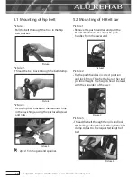
Page 14: ...and nuts Picture 3 2pcs 13 mm open end spanner 5 2 Mounting of H Belt bar Picture 1 Remove the push handles and pull the H belt attachment bar onto the push handles from the lower end Picture1 Picture 2 Fix the push handles in correct position and lock firmly Then fix the bar at the right position height The height should be level with the shoulders of the user Picture 2 Picture 3 Thread the belt ...

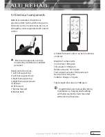
Page 15: ...port up 4 Right foot support down 5 Tilt back 6 Tilt forward 7 Recline forward 8 Recline back A holder for hand control can be mounted as accessory Weight of components Control box 1900 gram Tilt actuator 1650 gram Recline actuator 1610 gram Foot support actuator 984 gram each Hand control 240 gram Cable for charger 20 gram Total weight all inclusive 7388 gram An additional user manual describing ...

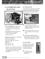
Page 16: ...n of options and will be delivered with separate mounting descriptions 6 2 Main wheels To mount the main wheel remove the quick release bolt from the hub bushing lead it through the centre of the main wheel and into the hub bushing while pressing the knob in center To check that the main wheel is properly attached to the hub remove the finger from the central knob and pull the main wheel If the ma...

Page 17: ...he front castors or front fork unfix the wheel and place it in the required position in the front fork Angle of bearing house Correctly adjusted angle of the front fork is important to achieve proper manoeuvring qualities of the wheelchair Unfix the two screws on the inside of the frame enough to adjust the the eccentric nuts Angle the bearing house so that it is 90 relative to the ground tighten ...

Page 18: ...s with 2 5 cm distance between them The seat depth can be adjusted from 40 50 cm Measured from front of seat plate to back rest tube without back rest cushion Onto the frame under the chair there is mounted an extra locking head for the gas strut The short locking head covers seat depth 40 cm 42 5 cm og 45 cm The long locking head covers seat depth 45 cm 47 5 cm og 50 cm There is also a long back ...

Page 19: ... Nm 6 mm Allen key 13 mm open end spanner If the user requires other back rest angles than what is standard it is possible to change the position of the gas strut in three positions under the chair in front When changing seat depth you also change the tipping point of the chair This can be prevented by changing the position of the main wheel in the main wheel bracket See chapter 6 6 6 9 Adjusting ...

Page 20: ...oth anti tips have the same length The gap between the anti tip wheels and the ground must be max 3 cm If the anti tip is positioned on the outside of the main wheel radius it will interfere with curbs and stairs The anti tip should always be used for the safety of the user 6 11 Adjusting arm supports Turn the release handle to the side and hold Adjust the armrest to the required height and releas...

Page 21: ...and can be angled in fixed positions As a standard the foot plates come with a locking bolt which makes the platesstronger Seepicturepage20 Thebolt canberemovedbyusingapairofcirclippliers Netti III HD has the following foot support alternatives Universal foot support Amputation support See chapter 5 for pictures Mounting of the foot support Raise the support a few degrees Fold the foot plates up H...

Page 22: ...he plastic lock on the right foot plate and place the lock over the bolt on the left foot plate To release the foot plate pull the plastic lock and lift the right foot plate up While making the adjustment there must be no load on the foot plates For outdoor use there should be a clearance of 4 5 cm between the foot plate and the ground Never stand on the foot plates due to the risk of tipping forw...

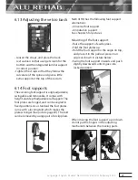
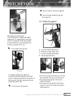
Page 23: ...y using an open end spanner between the pad and the bracket Find the required position and refix it Ill 6 14 B 13 mm open end spanner Never stand on the foot supports Never lift the wheelchair by the foot supports 6 15 Head support A Lever for depth adjustment B Wheel for angle adjustment C Lever for height adjustment D Head support bracke Place the squared nut in the trace of the head support bra...

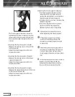
Page 24: ... head support and fix it in required position Adjusting the head support sideways The head support adapter can be moved both to the right and left giving the possibility to accomodate special needs for head support Untighten the four screws holding the adapter together Move the adapter to the required position and fix the adapter by tightening the screws diagonally Remember to release the levers w...

Page 25: ...akes The brakes are freely adjustable along the frame tube To activate the brake push the handle forward Ill 6 17 1 Ill 6 17 1 To release the brake pull the handle rearwards Ill 6 17 2 Ill 6 17 2 To reposition the brake loosen the two screws on the inside of the brake clamp For fine adjustment loosen the upper screw on the inside of the brakes Adjust the brake position and tighten the screws 5 mm ...

Page 26: ... applying the brake The wheelbase in drum brake is fitted with hand operated hub brakes to allow regulation of speed on hills and whilst travelling along These are located on the push handles To apply the brakes pull the brake levers 1 evenly and smoothly towards handle and bring the wheel base to a stop For to put on and lock the parking brake 2 press the lever 1 against the push handle and lock ...

Page 27: ...for an external neck support mounted in the car The chair is marked with stickers in 4 positions showing where to fix the straps Netti III HD has been successfully tested according to the requirement of ISO 7176 19 using a combined wheelchair an occupant restraint system W120 DISR developed by Unwin Safety Systems For furtherinformation www unwin safety com 6 18 Seat angle tilt The seat angle is r...

Page 28: ...luencing factors Also the position of the wheels will influence the driving ability The more weight placed over the main wheels the easier it is to manoeuvre If heavy weight is placed over the front castors the chair will be heavy to manoeuvre Companion If the user is left alone in the wheelchair always lock the brakes and secure that the anti tips are turned down Parking Increase the underneath s...

Page 29: ... on the step Turn the anti tip down 8 3 Driving techniques Step down Users drive down a step forwards This technique is only for very experienced users Check that the anti tip is turned up Drive towards the step Make a firm grip on the push rims and push fast forward so that the wheelchair comes down on all four wheels at the same time Turn the anti tip down Companions drive down a step forwards C...

Page 30: ... Move the upper part of the body forwards in order to maintain the balance of the chair Driving downhill Move the upper part of the body backwards to maintain balance of the chair Control the speed of the chair by clutching the push rims Do not use the brakes 8 5 Driving techniques Up stairs Always ask for assistance Never use escalators even if assisted by a companion With assistance backwards Ch...

Page 31: ...ir put the front castors safely down on the floor Turn the anti tip down If two companions are present one person can assist lifting in the front of the frame Do not lift the wheelchair holding onto the foot supports Do not lift the wheelchair holding onto the armrests 8 7 Transfer Techniques for transfering to from the wheelchair should be practiced well with the persons involved Here we give som...

Page 32: ...wards 8 8 Point of balance Adjust the point of balance by changing the position of the main wheel in the main wheel bracket Move the main wheel hub and the main wheel Chapt 6 6 Adjust the brakes Chapt 6 17 2 pcs 24 mm open end spanner 5 mm Allen key Whenthemainwheelsaremovedforward it will be easier to manoeuvre the wheelchair but the risk of tipping backwards increases The point of balance can al...

Page 33: ...stance to the main wheel influences the ability of the user to grip Contactyourdealertogetinformationabout push rims that fit your chair Alternative push rims may give a better grip but the friction may increase When using the hands to stop the chair the risk for burning of the hands increases A squeezing and trapping hazard of the fingers may occur when passing through narrow passages and if the ...

Page 34: ...ls Clean the wheelchair thouroughly after use We recommend washing the wheel chair in washing chamber at 85 C For small damages to the surface original surface paint can be ordered from the manufacturer Frequency Weekly Monthly Checkdefects damages E g breakage missing parts X Washing of wheelchair X Oiling of bearings X Washing of cushions X Check anti tip function X Checkbrakeadjustment X Check ...

Page 35: ...too hard Adjust the angle of the bearing house Heavy weight over the front castors Adjust the point of balance 6 4 6 5 The front castors are wobbling Too much weight over the front castors Adjust the point of balance by moving the main wheels back The front castors are not fixed properly Check that the front forks are fitted in the same height The angle of the bearing house might not be 90 6 4 6 4...

Page 36: ...ssionalinstallation and or repairs neglet wear from changes in wheelchair assemlies or instutions not approved by Alu Rehab or byuseofsparepartsdeliveredorproduced by third parties In such cases this guarantee shall be considered null and void 11 3 Claim Claim is to be addressed to the sales agent of the wheelchair Please note that sales documentation has to be filled in and signed correctly in or...

Page 37: ... the CE mark given by Alu Rehab A S Norway If this is the case the warranty given by Alu Rehab A S Norway will not be valid If any uncertainty about special fitting and adaptations please contact Alu Rehab A S 11 6 Combinations with other products Combinations of Netti and other products not manufactured by Alu Rehab A S Generally in these cases the CE mark of all the products involved will not be...

Page 38: ...uards add 2 5 cm Measured from front of seat plate to back rest hinge without cushion Using standard Uno back rest cushion subtract app 3 cm Measured from seat plate to top of back rest velcro The weight is including main wheels front castors foot supports and arm supports No cushion Recommended inflation pressure using air tyres is 60 65 PSI Max user weight is 160 kg When mounting accessories suc...

Page 39: ......

Page 40: ...UM0105UK Bedriftsvegen 23 NO 4353 Klepp Stasjon NORWAY Phone 47 51 78 62 20 Fax 47 51 78 62 20 E mail post alurehab com www alurehab com ...

Reviews: