TARGO DRIVES (TR SERIES)
|
ANTRIEBE TARGO (SERIE TR)
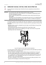
|
COMMANDES TARGO (SÉRIE TR)
10
ELECTRICAL CONNECTION OF THE DRIVE
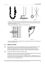
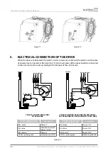
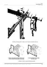
Figure 11
Figure 12
5.
ELECTRICAL CONNECTION OF THE DRIVE
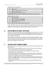
When the drives are delivered, the electric motor connection cable and the electric switch cable
of encoder are connected to the drive (
fig.
13). Electrical cables of the drive should be connected
to the external control unit according to the Manual of the control unit.
NC
S1
S2
M
1~
L1
CO
M
L2
L1
L2
N
BK BU BN YE-GN
NC
2
87
65 4 3 1
ENCODER
S3
S3
M
3
~
L1
L2
L3
L1
L2
L3
BK BU BN YE-GN
NC
S1
S2
NC
2
87
654 3 1
ENCODER
TR-3531-230E / TR-5020-230E /
TR-5024-230E
TR-5013-400E / TR-5020-400E / TR-5024-400E /
TR-10024-400E / TR-13018-400E / TR-13012-400E
COLOUR MARKING OF WIRES
OF ELECTRIC MOTOR CABLE
DESCRIPTION
COLOUR MARKING OF WIRES
OF ELECTRIC MOTOR CABLE
DESCRIPTION
BK—black
Phase L1
BK—black
Phase L1 (U)
BU—blue
Common contact of
phases (COM)
BU—blue
Phase L2 (V)
BN—brown
Phase L2
BN—brown
Phase L3 (W)
YE-GN—yellow-green
Protective earth (PE)
YE-GN—yellow-green
Protective earth (PE)
Figure 13

