background image

Installation Instructions

1170 N Red Gum St, Anaheim, CA 92806

©  ALUZ All Rights Reserved. ALUZ reserves the right to make changes or withdraw specifi cations without prior notice.

info@aluz.lighting

aluz.lighting

866.ALUZ.LTG | 714.535.7900

A1 Series 

|


Surface

ZIBI


Standard RGBW

(A1-ZIBI-STN-RGBW)

Page 1 of 12

Overview

4 / 29 / 2022 / Rev 2

READ ENTIRE GUIDE BEFORE STARTING INSTALLATION

Important Notice:


Verify correct luminaire was received with correct 

color temperature, voltage, and wattage before cutting or installing. 

ALUZ will not be responsible if incorrect luminaire is installed.

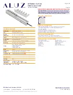
PRODUCT INFORMATION

• Lighting for wall washing, cove, edge, undercabinet, accent, displays 

• Line Voltage (Integral Driver) or Low Voltage (Remote Driver)  

• Color changing LEDs

• Available in 3 Watts up to 18 Watts Per Foot

• Product is shipped in 1’, 2’, 3’, and 4’ luminaires

• Available for outdoor rated installations

GENERAL FEATURES

Applications

Wall Washing Lighting

Lens

Tempered Clear Glass Lens

Optics & 

Asymmetric

10° - 60° or Asymmetric Optics

Length

Built to Order (2’, 3’, or 4’ Increments)

Construction

Aluminum Extrusion

Weight

2.3 lbs (1’), 5.6 lbs (2’), 7.9 lbs (3’), 11.2 lbs (4’)

Mounting

Mounting Clips (Sold Separately)

Listing

Dry or Wet (IP65 or IP67) Location

UL1598, CSA C22.2#250.0

UL8750, CSA250

UL2108, CSA C22.2 #9

Driver

Integral

Temperature 

Ratings

Operating / Startup: -20° to 48°C (-4° to 120°F)

Storage: -40° to 76°C (-40° to 170°F)

Installation Link

END VIEW / DIMENSIONS

2.52”

2.69”

• Electric Hammer Drill

• 14.4 to 28 Volt Cordless Drill         

• Phillips Bits  

• Utility Knife

• Electrical Cord   


• Marker 

• Wire Stripper

• Long Nose Pliers

• Drill Bits - Concrete or Wood

• Electrical Three Ways

• Safety Glasses

• Measuring Tape

• Laser Line or Chalk Line 


INSTALLATION TOOLS REQUIRED

ELECTRICAL REQUIREMENTS

• Line Voltage luminaires do not require a remote driver.

• Maximum load per line voltage fi xture is 320 watts per circuit.

ELECTRICAL

Dimming

DMX

Maximum Run

(Line Voltage

Integral Driver)

100’ 

(3W)

, 64’ 

(5W)

, 53’ 

(6W)

,

40’ 

(8W)

, 35’ 

(9W)

, 26’ 

(12W)

, 21’ 

(15W)

Luminaire Voltage

120V - 277V 

(UNV)

Summary of Contents for A1-ZIBI-STN-RGBW

Page 1: ...URES Applications Wall Washing Lighting Lens Tempered Clear Glass Lens Optics Asymmetric 10 60 or Asymmetric Optics Length Built to Order 2 3 or 4 Increments Construction Aluminum Extrusion Weight 2 3 lbs 1 5 6 lbs 2 7 9 lbs 3 11 2 lbs 4 Mounting Mounting Clips Sold Separately Listing Dry or Wet IP65 or IP67 Location UL1598 CSA C22 2 250 0 UL8750 CSA250 UL2108 CSA C22 2 9 Driver Integral Temperatu...

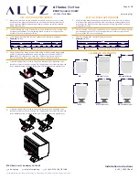
Page 2: ...ee mounting clips section for details Do not install mounting clips on uneven surfaces Use shims to level out height of mounting clips if necessary Do not install mounting clips after luminaires have been assembled Install mounting clips first then install luminaire into mounting clips Do not force luminaire into a space that is too small Do not force luminaire with cord grip into soffit Fig 3 Do no...

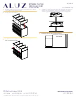
Page 3: ...MX Signal DMX White DMX Shield Sleeve DMX Blue DMX WIRING DIAGRAM Dry or Wet Location NOTES Default DMX address per RGBW luminaire DMX Address 001 Red DMX Address 002 Green DMX Address 003 Blue DMX Address 004 White Consult third party DMX commissioner to modify at time of installation Connection from DMX controller to luminaire must be made using a proper daisy chain connection per DMX 512 RDM st...

Page 4: ...ed applications b Screw mounting clips to surface then snap luminaire into mounting clips Install set screws to each mounting clip if applicable Set screws are required for downward facing outward facing and vertically mounted applications 3 Use a mounting clip at the junction between two luminaire segments Example 20 Run 4 Lay mounting clips along reference line and pre drill using an appropriate...

Page 5: ... weight of the luminaires 2 Use 1 mounting clip every 2 rounded up Use a minimum of 2 mounting clips per luminaire segment For vertical applications create a stopper at the bottom of the run to prevent sliding 1 Measure area where luminaire will be installed Use a laser line to create a reference line along installation area ensuring consistent alignment of mounting clips Mark location where each ...

Page 6: ...nting clips Refer to the Mounting Clips page for additional information 3 Lay mounting clips along reference line and pre drill surface using an appropriate drill bit for surface and screw size Recommendation 8 32 x 1 Screw Note Allow 1 4 clearance for lateral expansion of assembled mounting clips Only install mounting clips on flat even surfaces 4 If applicable connect disconnects between segment...

Page 7: ...er to Troubleshooting Continuity Test page for additional information 7 Verify wiring diagram then connect luminaire to power source 2 The number of required mounting clips differs for dry and wet location products Verify number of mounting clips is appropriate for installation environment before beginning installation Do not install luminaires with inadequate number of mounting clips Refer to the...

Page 8: ...crements diagram next page 2 Determine number of mounting arms needed Use a minimum of 2 mounting arms per luminaire Mount arms 6 from center of mounting plate to the end of luminaire Note Refer to Spacing Diagrams on next page 3 Mark location where mounting arms will be installed Screw arm base to surface using countersink screws of appropriate type and length for surface 4 Secure luminaire to mo...

Page 9: ...sink screws of appropriate type and length for surface 4 Secure luminaire to mounting plates by installing provided 6 20 countersink screws through countersink holes in the bottom of the plate Ensure luminaire is secured in place and spacing is accurate according to the Spacing Diagrams Shrink Tube Apply Heat 2 6 If applicable connect disconnects between luminaires Slide shrink tube over connector...

Page 10: ...rew 12 Min from Wall Shrink Tube Apply Heat 2 1 Determine number of louvers needed Louvers are available in 1 increments Specify total length of reflectors needed 4 If applicable connect disconnects between luminaires Slide shrink tube over connectors and apply heat The shrink tube will shrink down sealing the connectors Apply silicone around sealed connectors for a stronger seal 5 Mount luminaire...

Page 11: ...Min from Wall Shrink Tube Apply Heat 2 1 Determine number of reflectors needed Reflectors are available in 1 2 3 or 4 increments Specify total length of reflectors needed 4 If applicable connect disconnects between luminaires Slide shrink tube over connectors and apply heat The shrink tube will shrink down sealing the connectors Apply silicone around sealed connectors for a stronger seal 5 Mount l...

Page 12: ... short 3 Check to make sure cuts in the lightstrip are clean and not frayed causing positive and negative copper pads to touch 1 Turn off power before beginning Verify power is off by using a non contact circuit tester by others Touch the probe of the tester to the positive wire of the power source The tester will light up if an electrical current is detected 2 Setup your multimeter tester by othe...

Reviews: