Installation Instructions
4 / 11 / 2022 / Rev 1
1170 N Red Gum St, Anaheim, CA 92806
© ALUZ All Rights Reserved. ALUZ reserves the right to make changes or withdraw specifi cations without prior notice.
info@aluz.lighting
aluz.lighting
866.ALUZ.LTG | 714.535.7900
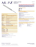
A8 Series
|
LED Tape
ZIZA
Standard
(A8-ZIZA-STN)
Page 11 of 12
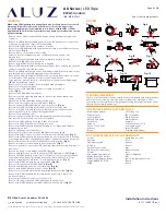
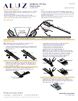
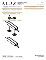
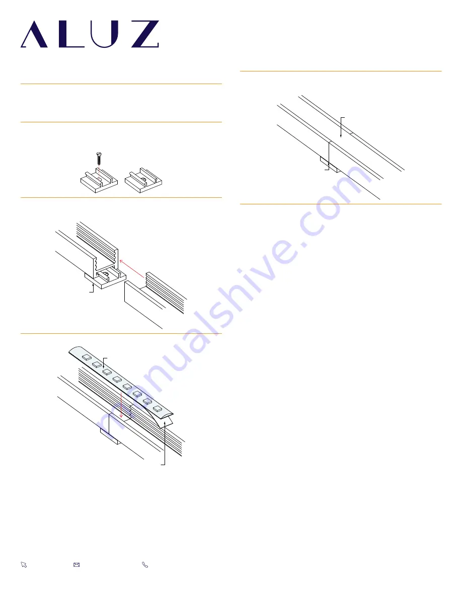
Mounting Fixture (Wet Location
Unassembled Mounting Clips)
MC
Remove adhesive backing
Install lightstrip into extrusions
Lens overlapping
Two extrusions meet
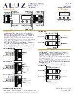
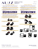
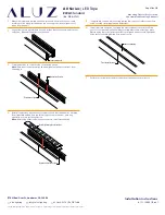
1
Measure area where luminaire will be installed. Use a laser line to create
a reference line along installation area, ensuring consistent alignment of
mounting clips. Mark location where each mounting clip will be installed
along reference line.
3
Lay mounting clips along reference line and pre-drill using an appropriate
drill bit for surface and screw size. Recommendation: 8/32 x 1” screw.
Note:
Allow 0.25” clearance for lateral expansion of assembled mounting
clips.Only install mounting clips on flat, even surfaces.
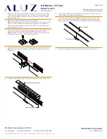
2
Mark location where mounting clips will be installed.
Note:
The number of required mounting clips differs for dry and wet location
products. Verify number of mounting clips is appropriate for installation
environment before installing. Do not install luminaires with inadequate
number of mounting clips.
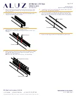
4
Screw mounting clips to surface, then snap extrusions into mounting clips.
Note:
Ensure extrusions are aligned. Misalignment will prevent lens from
snapping in.
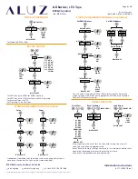
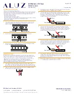
5
Screw mounting clips to surface, then snap luminaires into mounting clips.
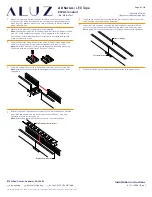
7
Install lens int o extrusion, overlapping where two extrusions meet. Plan
your cuts so that the lens will always overlap where two extrusions meet.
Overlapping lenses helps keep extrusions aligned and prevents light leaks.
8
Perform a continuity test before connecting luminaire to power source.
6
If applicable, connect disconnects between luminaires or solder connectors
using the steps from Application Guidelines.


