Installation Instructions
4 / 11 / 2022 / Rev 1
1170 N Red Gum St, Anaheim, CA 92806
© ALUZ All Rights Reserved. ALUZ reserves the right to make changes or withdraw specifi cations without prior notice.
info@aluz.lighting
aluz.lighting
866.ALUZ.LTG | 714.535.7900
A8 Series
|
LED Tape
ZIZA
Standard
(A8-ZIZA-STN)
Page 2 of 12
Product Care & Maintenance
Fig. 1
Fig. 2
Fig. 12
Fig. 3
Fig. 13
Fig. 4
<1.5”
Fig. 9
Fig. 14
Fig. 10
Fig. 15
Fig. 11
Fig. 7
Fig. 8
Fig. 5
Fig. 6
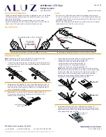
FIGURES
CLEANING MATERIALS
The use of solvents and/or cleaners which are not compatible with polycarbonate
will result in the softening, crazing, and/or cracking of the plastic part. This is
especially true of polycarbonate lamps and mounting bases which may be under
stress in their normal applications.
COMPATIBLE WITH POLYCARBONATE
• Mild soap and water
• Mineral Spirits
• Isobutyl Alcohol
• VM and P Naphtha
• Varsol No.2
• Mexane
• Freone TF and TE-35
• Ethanol
• Dirtex
• 2% Sol. Reg. Joy
• 10% Sol Bon Ami
• White Kerosene
• Methyl Alcohol
• Heptane
• Petroleum Ether / 65°C
• Isopropyl Alcohol
• Lacryl PCL-2035
Polycarbonate Cleaner
NOT COMPATIBLE WITH POLYCARBONATE
• Trichlor
• Gasoline
• Liquid Detergents
• Acetone
• Carbon Tetrachloride
• Pink Lux (Phosphate free)
• Triclene
• Chlorinated Hydrocarbons
• #1 & #3 Denatured Alcohol
• Methyl Ethyl Keytone (MEK)
• Texize-8006, 8129, 8758
• MIBK
• Liquid Cleaner – 8211
• Toluol
• Agitene
• Benzol
• Ajax
• Kleenol Plastics
• Lysol
• Stanisol Naphtha
• Oils
• Lemon Joy (phosphate free)
• Diversol
• Lestoil
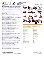
WARNING
When using LED Lightstrip for any application, basic safety precautions should
always be followed to reduce the risk of fi re, electric shock, and personal
injury. LED Lightstrip must be installed in accordance with the NEC or CEC as
applicable. ALUZ will not be responsible for any damage or malfunction caused
by the following:
• Ensure power is off before installation begins, during replacements, additions,
or repairs.
• Do not use LED Lightstrip if damaged, such as broken boards, loose connections,
or frayed wire insulation. Inspect before installing.
• Do not install LED Lightstrip in hazardous locations.
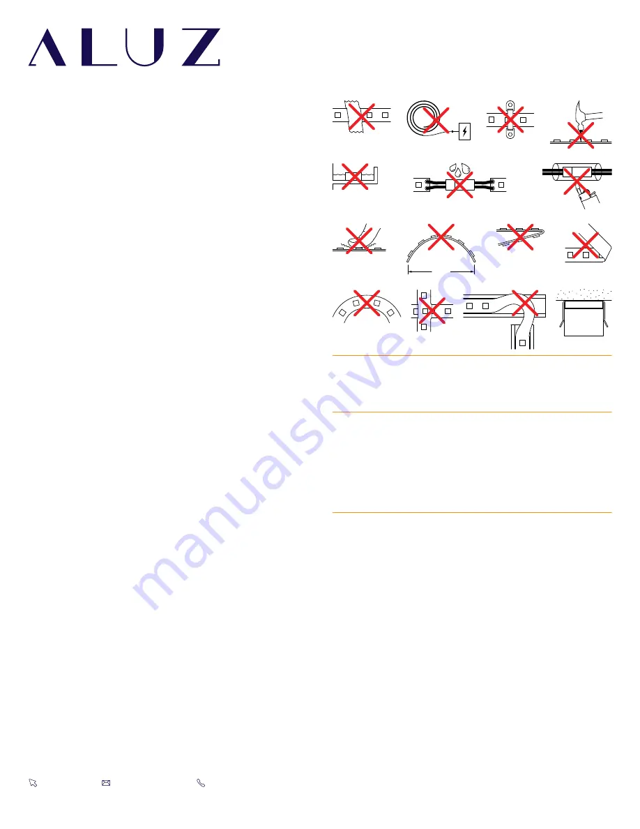
• Do not cover LED Lightstrip with any material, as it may cause LEDs to overheat,
melt, or ignite.
(Fig. 1)
• Do not paint on or over fi xture lens or LEDs.
Paint or any other substance on lens or LEDs will cause a shift in color
temperature.
• Soffi t must be evenly painted with a neutral white to avoid color shift.
• Do not modify LED Lightstrip in the fi eld.
• Do not overlap LED Lightstrip luminaires in any way.
• Only use LED Lightstrip with specifi ed rated voltages. Do not exceed the specifi ed
voltage for any LED Lightstrip luminaire.
• Do not use LED Lightstrip extrusion as a raceway for additional wire. Non-factory
feed through wires inside LED Lightstrip will void warranty.
• Ground Fault Circuit Interrupter (GFCI) protections should be provided on circuits
or outlets when LED Lightstrip is used for outdoor applications.
• Surge protector must be set up for electrical power system to avoid damaging
LED Lightstrip lighting system.
• Do not connect wires together, follow provided wiring diagrams.
• Do not cut wire while energized.
• Do not connect LED Lightstrip to power source while spooled or
coiled.
(Fig. 2)
• Do not exceed maximum run lengths.
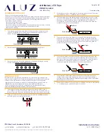
• Do not mount LED Lightstrip with staples, nails, or like means that might
damage the insulation.
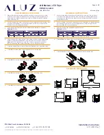
Mount with double-sided tape and mounting clips.
• Do not install mounting clips over LED diodes.
(Fig. 3)
• Do not penetrate LED Lightstrip with any foreign object.
(Fig. 4)
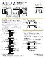
• Do not mount LED Lightstrip inside tanks or enclosures of any kind.
• Do not use improper screw head type on mounting clips. It will cause the
mounting clip to open up and become dysfunctional.
• Do not modify mounting clips.
• Do not mount fi xture with less than the minimum number of mounting
clips required. See mounting clips section for details.
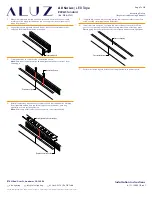
• Do not force LED Lightstrip into a space that is too small.
• Do not force LED Lightstrip with cord grip into soffi t.
• Do not install LED Lightstrip at an angle within a cove. Only install fi xtures
straight within a cove.
• Do not bend extrusion around radius.
• Do not submerge dry or wet location LED Lightstrip in any liquid.
• Do not install wet location in outdoor coves without proper drainage.
(Fig. 5)
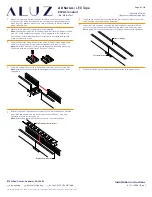
• Do not install LED Lightstrip in any area that is continuously exposed to flowing
or pooling water, such as underneath drain pipes, sprinklers, fountains, misters, etc.
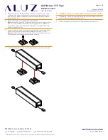
• Do not install connectors without shrink tube for wet location.
(Fig. 6)
• Do nut use a lighter or open flame to heat shrink tube.
(Fig. 7)
• Do not cut, puncture, or penetrate LED Lightstrip aluminum housing, end caps, or
lens covers.
• Do not drop, bang, or rest weight upon LED Lightstrip.
• Do not apply excessive pressure to any part of LED Lightstrip or LEDs.
(Fig. 8)
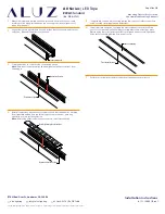
• Do not bend LED Lightstrip power cord or continuous connector past permitted
bend radius. Bending past permitted bend radius will break the seal of the
cordgrip or damage the insulation. 1.5” minimum bend radius.
(Fig. 9)
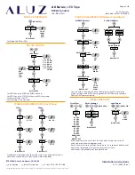
• Do not install LED Lightstrip in a zig zag fashion.
(Fig. 10)
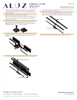
• Do not fold, crease, or twist LED Lightstrip.
(Fig. 11)
• Do not bend lightstrip along a horizontal plane.
(Fig. 12)
• Do not overlap LED Lightstrip at any location.
(Fig. 13)
• Do not cross or overlap extrusions and twist lightstrip to overlap.
(Fig. 14)
• Do not install LED Lightstrip in places where the power cord is subject to
continuous flexing.
• Do not twist continuous connector or power cord.
• Do not hold, carry, or suspend LED Lightstrip by the power cord.
• Do not install LED Lightstrip on ceilings without mounting clips.
(Fig. 15)


