Installation Instructions
4 / 11 / 2022 / Rev 1
1170 N Red Gum St, Anaheim, CA 92806
© ALUZ All Rights Reserved. ALUZ reserves the right to make changes or withdraw specifi cations without prior notice.
info@aluz.lighting
aluz.lighting
866.ALUZ.LTG | 714.535.7900
A8 Series
|
LED Tape
ZIZA
Standard
(A8-ZIZA-STN)
Page 3 of 12
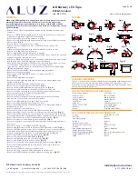
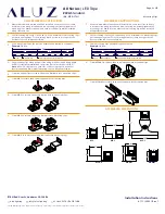
Dimming Protocol
& Wiring Diagrams
(DMX & DALI Driver - DRV100-E)
• Wire colors on diagram correspond to colors of driver terminals.
• DALI commissioning to be performed by a third party at time of
installation. ALUZ does not provide DALI commissioning.
• DALI Address must be set for each driver.
• A DALI Control System (by others) must be used to operate the lighting.
• Driver load not to exceed 100W.
• For best dimming performance, it is recommended to load drivers to a
minimum of 50% (50W) and a maximum of 80% (80W).
• Up to 28 drivers may be daisy chained together using shielded cable
specifi ed for DALI wiring.
• Ensure DIP Switch 1 is set to ON (Left) to activate 24V operation.
NOTES (DALI)
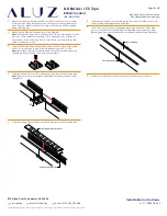
DALI OUTPUT
(TO NEXT DEVICE, IF APPLICABLE)
DALI INPUT
(FROM CONTROL SYSTEM, BY OTHERS)
TO LED LIGHTING
TO LED LIGHTING
INPUT VOLTAGE
INPUT VOLTAGE
DALI Daisy Chain
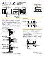
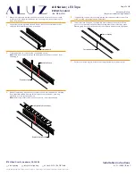
NOTES (DMX)
• Wire colors on diagram correspond to colors of driver terminals.
• Default DMX address of each luminaire is 001. Consult a third party
DMX commissioner to modify at time of installation. ALUZ does not
provide DMX commissioning.
• DMX Address must be set for each driver. Default DMX address is 001.
• A DMX Control System (by others) must be used to operate the lighting.
• The last driver in a daisy chain sequence must be terminated.
• Driver load not to exceed 100W.
• For best dimming performance, it is recommended to load drivers to a
minimum of 50% (50W) and a maximum of 80% (80W).
• Up to 28 drivers may be daisy chained together using shielded cable
specifi ed for DMX wiring.
• Ensure DIP Switch 1 is set to ON (Left) to activate 24V operation.
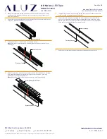
DIGITAL INTERFACE
DISPLAY
MODE
PLUS +
MINUS -
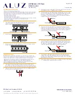
DMX+ INPUT (GRAY)
DMX- INPUT (GRAY)
DMX GROUND INPUT (GRAY)
LED SYNC+ OUTPUT (GRAY)
LED SYNC- OUTPUT (GRAY)
LED SYNC GROUND OUTPUT (GRAY)
COMMON / V+
(WHITE)
CHANNEL 1 / -
(RED)
DMX Wiring: Static White
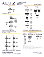
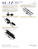
LED SUPPLY / +
(WHITE)
LED OUTPUT
1
/ R
(RED)
LED OUTPUT
2
/ G
(GREEN)
LED OUTPUT
3 / B
(BLUE)
LED OUTPUT
4
/ W
(YELLOW)
DMX+ INPUT (GRAY)
DMX- INPUT (GRAY)
DMX GROUND INPUT (GRAY)
LED SYNC+ OUTPUT (GRAY)
LED SYNC- OUTPUT (GRAY)
LED SYNC GROUND OUTPUT (GRAY)
DMX Wiring: RGBW
DMX+ INPUT (GRAY)
DMX- INPUT (GRAY)
DMX GROUND INPUT (GRAY)
LED SYNC+ OUTPUT (GRAY)
LED SYNC- OUTPUT (GRAY)
LED SYNC GROUND OUTPUT (GRAY)
COMMON / +
(WHITE)
CHANNEL 1 / WARM WHITE
(RED)
CHANNEL 2 / COOL WHITE
(GREEN)
DMX Wiring: Dynamic White (DWH)
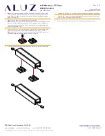
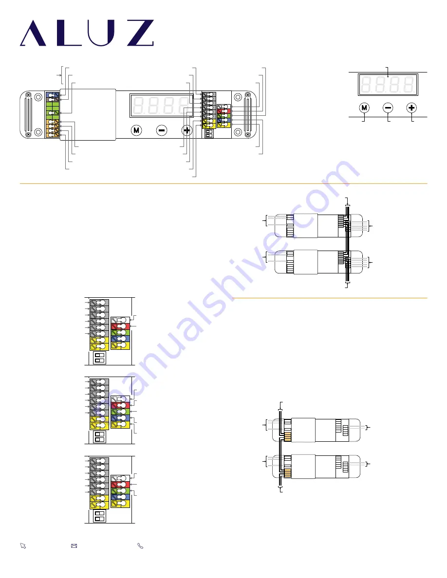
DMX OUTPUT
(TO NEXT DEVICE, IF APPLICABLE)
DMX INPUT
(FROM CONTROL SYSTEM, BY OTHERS)
INPUT VOLTAGE
INPUT VOLTAGE
TO LED LIGHTING
TO LED LIGHTING
DMX Daisy Chain
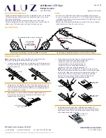
DIAGRAM OF DRIVER
NEUTRAL (BLUE)
LINE / HOT (BROWN)
GROUND (GREEN)
DMX+ INPUT (GRAY)
DMX- INPUT (GRAY)
DMX GROUND INPUT (GRAY)
DALI+ (ORANGE)
DALI- (ORANGE)
(WHITE)
CHANNEL
1
- (RED)
CHANNEL
2
- (GREEN)
DALI+ (ORANGE)
DALI- (ORANGE)
LEDSYNC GROUND OUTPUT (GRAY)
EXT+ INPUT (YELLOW)
LEDSYNC- OUTPUT (GRAY)
OUTPUT (GRAY)
EXT- INPUT (YELLOW)
CHANNEL
3
- (BLUE)
CHANNEL
4
- (YELLOW)
INPUT VOLTAGE
120
V -
277
VAC