background image

ALUZ

1170 North Red Gum Street, Anaheim, CA 92806

Phone: 800 921 2254 or 714 535 7900 | Fax: 714 535 7902 | info@aluz.lighting | aluz.lighting

©

 ALUZ All rights reserved. ALUZ reserves the right to make changes or withdraw specifi cations without prior notice.

Installation Instructions

Page 4 of 11

9 / 1 / 2021 / Rev 0

Tape

ZIZA

A8-ZIZA-TAPE

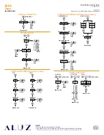
SET MODE

(HOLD 5 SEC.)

COLR

SHOW

DMX

DALI

DISPLAY OFF

1-1L RGB

2-2L RGBW

3-3L RGBA

4-4L RRGB

2-4L RGGB

1-4L CCWW

        CWWW

LOG

LIN

LED GROUPS

EXTERNAL INPUT

DIMMING CURVE

DISPLAY OFF

OFF

POTM

10V

SWIT

MODE OF OPERATION

SET LED GROUPS

STANDALONE OPERATION (Color / Show)

STANDALONE OPERATION (Network Operation)

HUE

0 - 1535

WHITE

0 - 510

INTENSITY

0 - 255

DISPLAY OFF

Color

SHOW

00 - 20

SPEED

-99 - 99

INTENSITY

0 - 255

DISPLAY OFF

Show

DMX ADDRESS

NETWORK RESOLUTION

DMX TERMINATION

NETWORK SETUP

INTERPOLATION

1 - 512

8 BT

16 BT

YES

NO

AUTO

MANU

OFF

VID

COLR

WHIT

GLOW

DISPLAY OFF

Set DMX Address

NO ADDRESS ADDRESS SET

NO. OF BALLASTS

DISPLAY OFF

Set DALI Address

OTHER FUNCTIONS

NO

SOFT

HARD

LOCK DRIVER

DISPLAY OFF

(HOLD 5 SEC.)

Lock Driver

TEST

DISPLAY OFF

R 1 SEC

G 1 SEC

B 1 SEC

B 1 SEC

W 1 SEC

RGBW 1 SEC

R 1 SEC

G 1 SEC

B 1 SEC

W 1 SEC

RGBW 1 SEC

Visual Test

RESET

PRESS MENU

(HOLD 5 SEC.)

DISPLAY OFF

Reset

Driver Functions (DMX & DALI Driver - DRV100-E)

Summary of Contents for A8-ZIZA-TAPE

Page 1: ...late Load Multiply Watts per Foot x Length in Feet Example 4 5W x 10 45W Choose a driver from catalog Example 60 Watt Driver Determine maximum driver distance using Maximum Wire Length Table on drivers page Example 45 watts is between 40W and 60W Using 14 wire maximum distance is 37 from driver to first LED Electric Hammer Drill 14 4 to 28 Volt Cordless Drill Phillips Bits Utility Knife Electrical ...

Page 2: ... inside LED Lightstrip will void warranty Ground Fault Circuit Interrupter GFCI protections should be provided on circuits or outlets when LED Lightstrip is used for outdoor applications Surge protector must be set up for electrical power system to avoid damaging LED Lightstrip lighting system Do not connect wires together follow provided wiring diagrams Do not cut wire while energized Do not conn...

Page 3: ...ot Brown Neutral Blue V V Common Channel 1 Ground Green Line Hot Brown Neutral Blue V V Common Channel 1 DALI Output to next driver if applicable DALI Input from control system by others DALI DALI DALI DALI DALI DALI TYPICAL DAISY CHAIN LAYOUT DALI STATIC COLOR DALI commissioning to be performed by a third party at time of installation ALUZ does not provide DALI commissioning Wire colors on diagra...

Page 4: ...F OPERATION SET LED GROUPS STANDALONE OPERATION Color Show STANDALONE OPERATION Network Operation HUE 0 1535 WHITE 0 510 INTENSITY 0 255 DISPLAY OFF Color SHOW 00 20 SPEED 99 99 INTENSITY 0 255 DISPLAY OFF Show DMX ADDRESS NETWORK RESOLUTION DMX TERMINATION NETWORK SETUP INTERPOLATION 1 512 8 BT 16 BT YES NO AUTO MANU OFF VID COLR WHIT GLOW DISPLAY OFF Set DMX Address NO ADDRESS ADDRESS SET NO OF ...

Page 5: ...lder covering wire and pads Weller 0 50 solder wire Solder covering wire and pads Cover connections with silicone SOLDERING GUIDE 1 Cut lightstrip to desired length Include both sets of solder pads by cutting to the left or right of designated markings allowing more space for soldering 4 Solder lead wires to solder pads on the end of lightstrip Solder the positive wire Red or Black with ridged jac...

Page 6: ... clip every 6 or 1 mounting clip every 4 if lightstrip is facing out or down 4 Always use a mounting clip at the very beginning and very end of each run 5 Lay mounting clips along reference line and pre drill using an appropriate drill bit for surface and screw size Recommendation 8 32 x 1 screw 6 Screw MCS mounting clips to surface securing lightstrip to surface 94 13 MCS 51 78 MCS WET 90 78 MCS ...

Page 7: ...om reel using a wire puller stand and cut to size as needed Note Include both sets of solder pads if soldering connectors Refer to Soldering Guide for details 7 If applicable connect disconnects between luminaires or solder connectors using the steps from Application Guidelines 3 Remove adhesive backing from lightstrip and stick in place along chalk line ensuring lightstrip is securely mounted and...

Page 8: ...unting channels Mark location where mounting channels will be installed along reference line 5 Ensure lightstrip is secured in place and is free of twists tangles creases or bumps 2 Lay extrusions along chalk line and drill at least 3 countersink holes per extrusion Drill additional holes as needed 3 Screw extrusions to surface using countersink screws Note Ensure extrusions are aligned Misalignme...

Page 9: ...unting channels will be installed along reference line 2 Mark location where mounting clips will be installed Note The number of required mounting clips differs for dry and wet location products Verify number of mounting clips is appropriate for installation environment before installing Do not install luminaires with inadequate number of mounting clips 3 Prepare for mounting by removing adhesive ...

Page 10: ...annels will be installed along reference line 5 Ensure tube is secured in place 2 Lay extrusions along chalk line and drill at least 3 countersink holes per extrusion Drill additional holes as needed 6 If applicable position jumper wires between luminaire segments as needed Note Refer to Design Guidelines Continuous Run Wet Location for details 3 Screw extrusions to surface using countersink screw...

Page 11: ... and negative copper pads to touch 1 Turn power off before beginning Verify power is turned off by using a non contact circuit tester Touch the probe of the tester to positive wire of the power source The tester will light up if an electrical current is detected 2 Setup your tester First insert the black probe lead into the COM jack then insert the red probe lead into the VΩ jack Metal Flakes Fore...

Reviews: