background image

USING YOUR HEATER

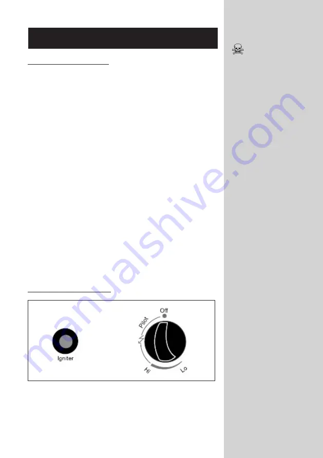
Lighting of the Patio Heater:

1.  Check all the connections for leaks or damage prior to each 

use.

2.  Open the gas cylinder valve 1½ turns (anti-clockwise).

3.  Press down the variable control knob and hold for 30 sec-

onds. While holding down the variable control knob, press 

the igniter button several times until the pilot flame lights. 

Release the variable control knob after the pilot flame lights. 

Note: 

• 

If a new tank has just been connected, please allow at 

least one minute for the air in the gas pipeline to purge out 

through the pilot hole. 

• 

When lighting the pilot flame make sure that the variable 

control knob is continuously pressed down while pressing 

the igniter button. Variable control knob can be released 

after the pilot flame lights. 

• 

After the pilot flame lights, turn the variable control knob to 

maximum position and leave it there for 5 minutes or more 

before turning the knob to desired temperature position. 

4.  Gently push in the control knob on the heater and turn it to 

the “PILOT” position. (Counter clockwise 90°)

5.  After the pilot flame lights, turn the variable control knob to 

maximum position and leave it there for 5 minutes or more 

before turning the knob to desired temperature position. 

6.  If the heater does not ignite the first time, wait for 5 minutes 

and repeat the lighting instructions. If you still experience 

ignition problems, contact 086 100 ALVA (2582) for assis-

tance.

Turning the Patio Heater Off:

1.  Turn the variable control knob to PILOT position. 

2.  Press and turn the variable control knob to OFF position. 

3.  Close the cylinder valve (clockwise).

4.  DO NOT attempt to relight the heater for at least 10 minutes.

Smoke and odour 

caused by the heating 

of oils used during 

manufacturing will

occur when lighting 

the heater for the first 

time. This is normal 

and there is no

reason for alarm.

Avoid inhaling the 

fumes!

The smoke and odour 

should dissipate within 

3 - 4 minutes.

Check the heater 

immediately if any of 

the following occurs:

• 

The heater does 

not reach tem-

perature.

• 

The burner 

makes popping 

noise during use 

(a slight noise is 

normal when the 

burner is extin-

guished).

• 

Smell of gas in 

conjunction with 

extreme yellow 

tipping of the 

burner flames.

13


Summary of Contents for GHP20

Page 1: ......

Page 2: ...s Follow the Leak Testing procedure outlined under LEAK TEST Leak test the patio heater every year or if you ever smell gas NEVER use this heater with a cylinder other than the size recommended DO NOT...

Page 3: ...EMBLY HEATER SET UP LOCATION LEAK TEST USING YOUR HEATER FLASHBACK Flames in the burner tube CHANGING YOUR CYLINDER MAINTENANCE FREQUENTLY ASKED QUESTIONS TROUBLE SHOOTING GUIDE SPECIFICATIONS AFTER S...

Page 4: ...r please read through this manual and make sure you understand everything If you are not sure call 086 100 ALVA 2582 or visit www alva co za for help This heater is a safe and efficient form of heatin...

Page 5: ...RAM 1 2 Flame Screen 3 Glass Tube 4 Protective Guard 5 Upper Support 6 Front Panel 7 Side Panel 8 Lower Support 9 Bottom plate Refer to your Key on the index page 2 2 1 4 3 6 5 8 7 9 2270 mm 900 mm 65...

Page 6: ...EXPLODED VIEW 3 A B C D E F G H L K J I M N...

Page 7: ...1 Gas Hose and Regulator x1 Control Box Assy x1 Lower Support x4 Block Belt x1 Wheel Assembly x1 Bottom plate x1 4 A B C D E F G H I J K L M N Wing Nut x3 Small flat washer 6 x6 Stud x3 3 16 Screw x38...

Page 8: ...ater tightens to the left hand side anti clockwise Figure A If you have bought a new gas cylinder the cylinder needs to be purged emptied out before it s first use If it is not purged of air the heate...

Page 9: ...bolts that have come loose Assemble the wheel assembly to the bottom plate Fix the wheel assembly to the bottom plate using 4pcs bolt M6X12 and 4pcs 6 Fig B Nose cone sealing washer STEP 1 M EE FF...

Page 10: ...rt and base Insert the pins of the control box assy to the holes of upper support press to secure the pins Using 4pcs screw 3 16 screw to secure the upper support and control box assembly Assemble blo...

Page 11: ...Assemble the middle support Insert the 4pcs upper support to the lower support Secure them with 8pcs screw 3 16 3 16 8 STEP 4 STEP 5 D DD B DD...

Page 12: ...s tube through the hole of the lower plate cover and onto the middle plate Check and ensure that the glass tube is positioned properly and is completely covering the center hole of the middle plate ST...

Page 13: ...hooks of the protec tive guard onto the holes in the supports Secure the protective Attach the three side panels to the heater using 18pcs 3 16 screws 10 STEP 8 STEP 9 Note Do not cover the front sid...

Page 14: ...e the heater Secure the cylinder with the block belt tightly Perform a leak test before use 11 STEP 10 STEP 11 Warning Ensure the hose does not make contact with any high temperature surfaces or it ma...

Page 15: ...er from the gas cylinder Tighten the connection and retry the leak test If you are unsure or if you cannot tighten the connection place the cylinder outside in a cool well ventilated area and contact...

Page 16: ...it to the PILOT position Counter clockwise 90 5 After the pilot flame lights turn the variable control knob to maximum position and leave it there for 5 minutes or more before turning the knob to desi...

Page 17: ...oblem persists have the heater checked by a qualified technician CHANGING YOUR CYLINDER Make sure you cylinder valve is closed by turning it clockwise Allow the heater to fully cool before replacing t...

Page 18: ...before attempting to light the heater You might have to replace the parts if the heater does not ignite The airflow must not be obstructed Keep the controls and burner passage clean Clean with a soft...

Page 19: ...ppliances give off an odour This could be harmful if inhaled for extended periods of time This smell is normal and it does not mean that you have a gas leak The smell of raw gas just before you ignite...

Page 20: ...GUIDE Burner will not light Pressure is low Opening blocked Control not ON Thermocouple bad Not in correct location Tank near empty Refill LPG tank Remove and clean Turn valve to ON Replace thermocou...

Page 21: ...MANUFACTURED AND DISTRIBUTED BY Alva Marketing Pty Ltd P O Box 30014 Tokai 7966 Tel 021 442 1540 E mail info stingray co za www alva co za StingrayGroupSA www facebook com AlvaGas TOLL FREE NUMBER 08...

Reviews: