background image

Supervisor 3500 Installation Instructions

PUD3673R1-1 

       For assistance: support@alvaradomfg.com  +1 (909) 591-8431  

Page 19


The included crossover cable interconnects communication signals 

and low-voltage 24VDC between the master and slave cabinets.  

The default length of the crossover cable included with the SU3500 

is 8'. Optional crossover cable lengths of 20' and 40' are available. 
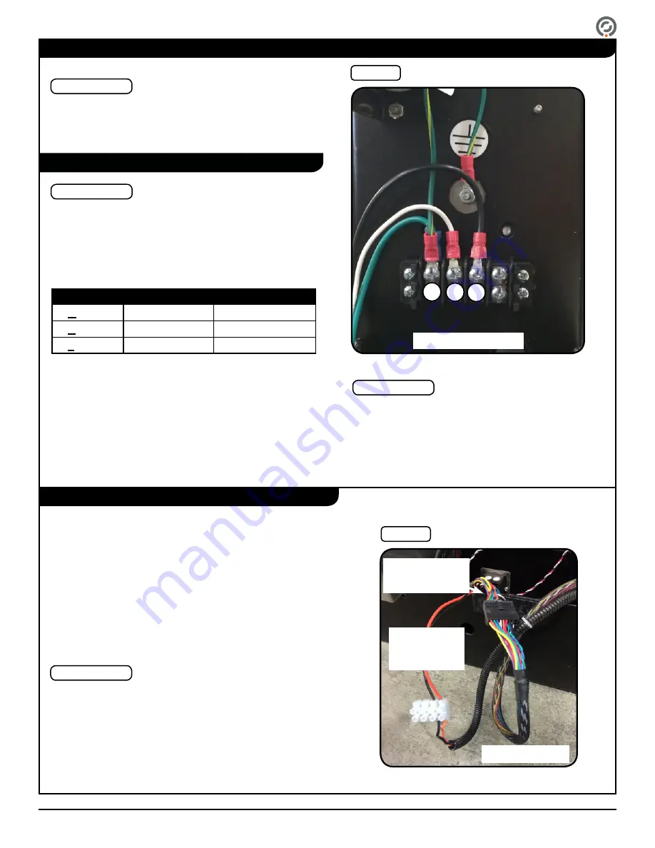
1.  Locate the low-voltage terminal block tucked in bottom of the 

center base in the master cabinet [Figure 18].

2.  Insert the 24VDC positive wire (orange) and the negative wire 

(black) into the terminal block, matching the colors with the 

other side and tighten [Figure 18].

3.  Connect the data connector from the crossover cable to the 

data connector in the master cabinet [Figure 18].

4. 

Repeat Steps 1 – 3 for the slave cabinet.  

Wiring Instructions

IMPORTANT

110VAC and 220VAC primary power (unless ordered otherwise) 

must be hard wired in place. It is strongly recommended that a 

licensed electrician perform this procedure in accordance with 

all applicable local codes.

The primary wiring lines for 110VAC and 220VAC consist of the 

following:  

Terminal

110V

220V

G

round

Green

Green/Yellow

N

eutral

White

Blue

L

ine

Black

Brown

1.  Locate the pre-installed power terminal block and attached 

wiring (located inside the leg on master / center cabinets) 

[Figure 17]. 

2.  Attach each power wire to the power terminal block with 

the corresponding color exiting on the other side.

3.  Using a Phillips-head screwdriver, tighten each terminal 

block connection.

Primary Power

NOTE

Crossover Cable

Fig. 17

Power Terminal Block

Fig. 18

Crossover Cable & Low Voltage

The orientation of the pre-installed terminal block may 

differ from what is shown in [Figure 17]. On some 

installations, the terminal block is rotated 90 degrees. 

Some installations may also included a three-pole power 

terminal block.

NOTES

Crossover Cable  

(packaged separately)

Data/Communication 

Cable (tucked in the 

bottom of the cabinet)

24VDC Power 

and Ground Wire 

(tucked in the 

bottom of the 

cabinet)

G N L

110VAC version shown

Center cabinets have two crossover cable connectors tucked 

in the base: one labeled MASTER and one labeled SLAVE. 

Crossover cables are used to interconnect master and slave 

connectors. Refer to Appendix D for crossover cable connection 

diagrams.

FOR EXTERNAL DC POWER SUPPLY INSTALLATION 

INSTRUCTIONS, REFER TO APPENDIX C ON PAGE 34.

NOTE

Summary of Contents for SU3500

Page 1: ...Inc 12660 Colony Street Chino CA 91710 Phone 1 909 591 8431 Fax 1 909 628 1403 support alvaradomfg com www alvaradomfg com PUD3673R1 1 Supervisor 3500 SU3500 Optical Turnstile with Motorized Barrier W...

Page 2: ...Turnstile Layout 14 Baseplate Assembly Optional 15 Installation Instructions 16 Anchoring the Turnstile 16 Internal Card Reader Installation 18 Wiring Instructions 19 Primary Power 19 Crossover Cable...

Page 3: ...Alvarado parts to repair a damaged turnstile Closely follow the handling instructions for moving or lifting the turnstile during installation Power off the turnstile before connecting or disconnectin...

Page 4: ...er Cabinets are used to create additional lanes for multi lane configurations Each additional lane includes the parts below Single Lane Parts List Center Cabinet Parts List Per Center Cabinet Concrete...

Page 5: ...atus display that communicates lane status to the user A card reader is normally installed during installation underneath the lid below the user status display Center cabinets contain both master and...

Page 6: ...enabled Running Ethernet cabling to the SU3500 provides a number of benefits 1 It allows implementation of Alvarado s TCP IP control and monitoring software 2 It allows easy implementation of SU3500...

Page 7: ...g com 1 909 591 8431 Page 7 For ease of installation and service allow 6 of space between cabinets and walls or other surfaces All dimensions are approximate Space Requirements 22 Lane Plan View Eleva...

Page 8: ...ease of installation and service allow 6 of space between cabinets and walls or other surfaces All dimensions are approximate Space Requirements 36 Lane Elevation View Plan View Footprint Drawing Fig...

Page 9: ...uggests the use of surge protection on the high voltage power line to further protect electronics Fig 5 SU3500 Conduit Lines Seal the floor area around the conduits running up and into the cabinets Th...

Page 10: ...on Card readers or other physical access devices may be installed in the reveal under the lid on either or both right hand sides of the lane Card readers physical access devices are not supplied by Al...

Page 11: ...ocation they will be installed 2 Unlock each end panel with the key provided To remove slide each unlocked end panel up slightly and then pull it away from the cabinet See Figure 6 for more details Wh...

Page 12: ...7 for more details Removing a Side Panel Slide Across Pins Lift to Free Side Panel from Pins FIGURE 4 3 0 2 Removing the Side Pane Removing a Side Panel Slide Across Pins Lift to Fre Panel fro FIGURE...

Page 13: ...r cabinet if applicable 1 Remove each shim after the cabinet panel has been removed by pulling firmly on the orange pull tab Figure 9 IMPORTANT Motor Shim 1 per motor Orange Pull Tab Fig 9 Removing Mo...

Page 14: ...witch should always be located on the secured side Unsecured Side Unsecured Side Secured Side Secured Side Power Key Switch Power Key Switch Power Key Switch Power Key Switch Power Key Switch Power Ke...

Page 15: ...led with appropriate holes as needed for concealment Determine which side plate to remove and remove it by unfastening the 4 screws as shown in Figure 12 Place the baseplate carefully in the marked lo...

Page 16: ...ptimum performance Use the following procedure to square each cabinet with respect to the floor and other cabinets A Measure the distance from the inside wall of one cabinet to the inside wall of the...

Page 17: ...of the anchor must be inserted into the hole first Use a hammer to tap the anchors into place if needed Ensure that the anchors are flush with the concrete floor 6 If not already done pull all wires A...

Page 18: ...ot pull this power from the SU3500 power supply 1 Locate the card reader mounting bracket Figure 16 2 Using a Phillips head screwdriver remove the card reader bracket mounting screws Figure 16 3 Insta...

Page 19: ...consist of the following Terminal 110V 220V Ground Green Green Yellow Neutral White Blue Line Black Brown 1 Locate the pre installed power terminal block and attached wiring located inside the leg on...

Page 20: ...ned dry contacts SDC All input signals must be normally open N O voltage free dry contacts with the exception of the fire alarm input which can be configured via jumper on the I O control board to acc...

Page 21: ...or one authorized passage until passage occurs or timeout 10 EXTALRX Unauthorized Presence Exit MDC An output occurs when there is entry into the lane area from the exit direction without authorizatio...

Page 22: ...Key Control If this option has been ordered for your turnstiles two 3 position key switches are installed on the turnstile Turning the key to one of the three positions allows each turnstile directio...

Page 23: ...ate the ENTPAS and GND terminals 2 Using a wire jumper connect the ENTPAS and GND terminals Figure 21 Exit Direction 1 Locate the EXTPAS and GND terminals 2 Use a wire jumper to connect the EXTPAS and...

Page 24: ...es can be found in the SU3500 User Guide Flashing Passage Mode Description User Status Display Open Closed Status Light Controlled Passage The barrier wings are closed securing the lane Upon receipt o...

Page 25: ...Appendix A on Page 29 for instructions on setting the barrier wing Home Closed Position The keys to power the turnstile ON OFF are packaged in the hardware box that was shipped with the turnstile Pow...

Page 26: ...Unsecured Side Unauthorized Entry shown Authorized Entry shown Secured Side Unsecured Side TEST PROCEDURE TURNSTILE RESPONSE Enter the turnstile without authorization Unauthorized Entry Exit alarm so...

Page 27: ...Free Passage direction Barriers open away from the user entering the turnstile Barriers close after passage completion Enter the turnstile User Status Light red icon is illuminated Open Closed Status...

Page 28: ...as shown in Figure 25 Turning the key to one of three positions overrides all existing settings placing the turnstile in Controlled Passage mode Free Passage mode or No Passage mode depending on the...

Page 29: ...ch programs and files field 5 Enter the following command ping XXX XXX XXX XXX where XXX XXX XXX XXX is the IP address of the turnstile Figure 28 6 A successful ping will result in the message shown i...

Page 30: ...s move smoothly between the open and closed positions 3 Access Control Integration Installed card readers are successfully reading credentials Valid credentials are activating the turnstile 4 Barrier...

Page 31: ...ctions Barriers operate erratically Barriers do not move Digital position encoder is not in place Verify the digital position encoder is secured to the pulley shaft with all the locks tabs in place Fi...

Page 32: ...operation mode 2 Press the Test Mode button for two seconds The D2 LED will be lit solid You are now in test mode Figure A1 3 Move the barrier wing a couple of inches in both directions and then plac...

Page 33: ...uration Three Lane Configuration LANE 2 LANE 2 LANE 3 LANE 1 LANE 1 Master Cabinet Master Cabinet Center Cabinet Center Cabinet Slave Cabinet Center Cabinet Slave Cabinet Symbology Description Conduit...

Page 34: ...not provided Wire gauge recommendations for 30 50 and 100 ft runs are provided on Page 36 If your installation requires runs beyond 100 ft ensure wire gauge is appropriate and in compliance with local...

Page 35: ...onduit holes on the enclosure Figure C3 4 Locate the pre installed primary power terminal block Figure C3 There is one primary power terminal block per enclosure 5 Attach each primary power wire to th...

Page 36: ...urnstiles Fig C4 Power Supply Output Terminal Block Fig C5 Turnstile Power Terminal Block The 24VDC V and GND V terminals are common NOTE If connecting to multiple turnstiles it is recommended to labe...

Page 37: ...ort alvaradomfg com 1 909 591 8431 Page 37 LANE 1 MASTER CABINET CENTER CABINET SLAVE CABINET CENTER CABINET LANE 2 LANE 3 110VAC 220VAC INPUT POWER SUPPLY ENCLOSURE 24VDC OUTPUT TO CIRCUIT BREAKER Ex...

Page 38: ...ation Instructions Page 38 For assistance support alvaradomfg com 1 909 591 8431 PUD3673R1 1 24VDC CONDUIT HOLES 110 220VAC CONDUIT HOLE Power Supply Enclosure Dimensions 15 80 401 4 9 50 241 3 6 23 1...

Page 39: ...ble Connection Diagrams MASTER SLAVE Master Cabinet Slave Cabinet SLAVE SLAVE MASTER MASTER Master Cabinet Center Cabinet Slave Cabinet LANE 1 LANE 2 SLAVE SLAVE SLAVE MASTER MASTER MASTER Master Cabi...

Page 40: ...vision Date Author Description 1 0 07 18 14 A Flores Initial creation Replaces SU3500 Installation and Maintanence Guide PUD2890 1 1 11 13 15 A Flores Updated crossover cable length to 8 Appendix B Mu...

Page 41: ...PUD3673R1 1 For assistance support alvaradomfg com 1 909 591 8431 Page 41 This page left intentionally blank...

Page 42: ...2014 Alvarado Manufacturing Company Inc This work may not be reproduced published or redistributed in whole or in part without the express prior written permission of Alvarado...

Reviews: