TAS12-AS1 & TAS12P-AS1 Installation Instructions
Page 8
For Assistance: support@alvaradomfg.com +1 (909) 591-8431 PUD3677R1-0
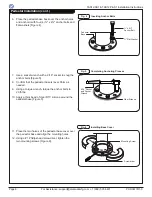
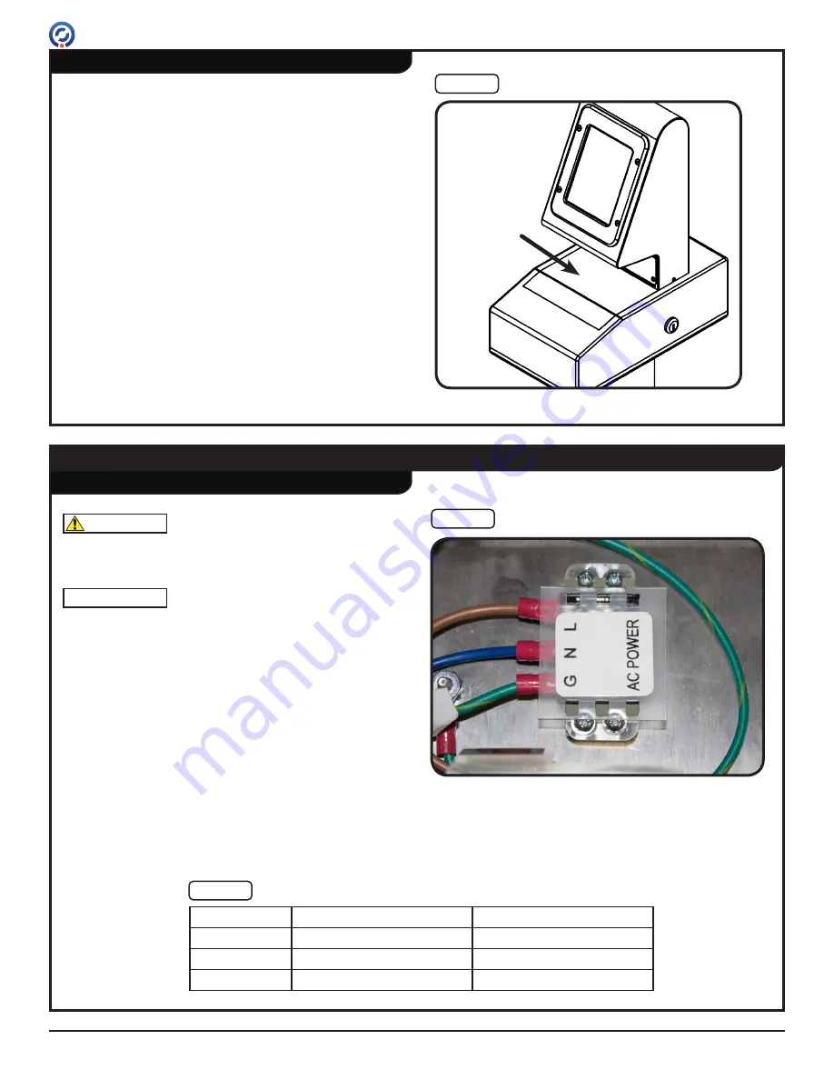
7. Remove the plastic backing off the self-adhesive
blackout pad. Center the blackout pad under
TAS12 and press firmly into place [Figure 9].
Mounting the TAS12 Unit (cont.)
Blackout
Pad
Fig. 9
Blackout Pad
Wiring Instructions
Primary Power
It is recommended that a licensed technician perform the
following steps.
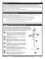
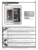
1. Locate the terminal block inside the pedestal box.
[Figure 10].
2. Remove the protective cover from the terminal block.
3. Attach ring connectors to the primary power LINE,
NEUTRAL, and GROUND wires.
4. Using a precision screwdriver, connect the LINE,
NEUTRAL, and GROUND primary power wires to
the terminal block. Refer to [Table 1] for 110V & 220V
power configurations.
5. Install the protective cover onto the terminal block.
NOTE
WARNING
Ensure primary power is turned OFF at the
circuit breaker.
Fig. 10
Primary Power Terminal Block
Table 1
110V & 220V Power Configurations
110V
220V
(L)INE
BLACK
BROWN
(N)EUTRAL
WHITE
BLUE
(G)ROUND
GREEN
GREEN / YELLOW
(TAS12-AS1 shown)


