Mobile Pivot Rack
Set-Up & Usage Instructions
For model BPR026
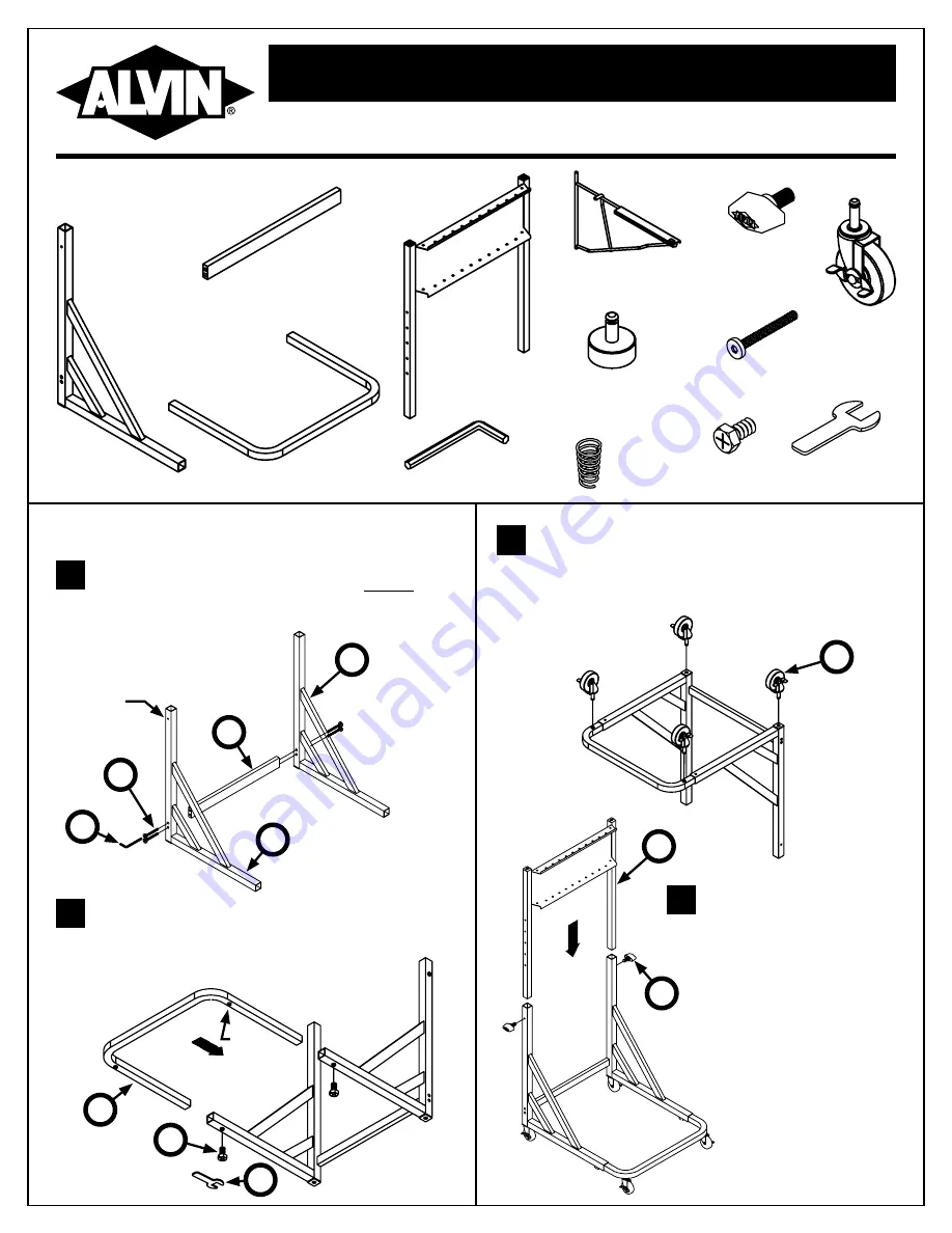
Parts Included:
Identify left and right side frames (
A
) by the single hole
at the top of each tube. These holes should face out.
Connect side frames together using back crossbar (
B
)
and four Allen bolts (
I
) as shown in
Figure 1
. Keep bolts
slightly loose for now.
Turn entire assembly upside down on a carpet or other
scratch-free surface. Insert wheels (
G
) as shown in
Figure 3
. Be sure each wheel is fully seated. If non-mobile
application is desired, install footglides (
H
) instead of
wheels. Return assembly to upright position.
With back panel oriented as
shown in
Figure 4
, slide back
frame (
D
) into side frame
tubes. Using a set of holes
somewhere in the middle,
insert adjustment knobs (
F
)
and tighten gently. Final height
adjustment will be made later.
With caster holes facing down, slide front U
frame (
C
) most of the way into side frame tubes
as shown in
Figure 2
. Insert hex bolts (
L
) and
tighten gently with wrench (
M
). The final position
of the front U frame will be adjusted later.
1
3
4
2
Assembly Instructions:
Figure 1
Figure 3
Figure 2
Figure 4
A
2pcs Side
Frame, Left
and Right
B
1pc Back
Crossbar
C
1pc Front
U Frame
D
1pc Back
Frame
E
12pcs Pivot
Bracket
F
2pcs
Adjustment
Knob
G
4pcs
Wheels
H
4pcs
Foot Glides
I
4pcs
Allen Bolt
K
12pcs
Springs
J
1pc Allen
Wrench
Left
A
x4
I
Hole
faces
out
Caster
Hole
x4
G
x2
L
M
x2
F
B
C
J
Right
A
D
L
2pcs
Hex Bolts
M
1pc Hex
Wrench


