©2012
Alvin & CompAny, inC.
• P.O. Box 188, Windsor, CT 06095-0722
Phone: 860-243-8991 • Toll-Free: 800-444-2584 • Fax: 860-242-8037 • Toll-Free Fax: 800-777-2896
www.alvinco.com
LIT-A12055 5/12
Limited Lifetime Warranty
Alvin & Company warrants its Blueprint Racks to be free from defects in workmanship and materials under normal use for the lifetime of the product for as long
as the original purchaser owns it. Should service be required by reason of any defect or malfunction, Alvin will repair, provide replacement parts, or at its discre-
tion, replace the product without charge subject to verification of the defect or malfunction. This warranty is valid only if the product is used for the purpose for
which it was designed. It does not cover products that have been damaged by negligence, misuse, or accident or which have been modified or repaired by unau-
thorized persons. Coverage is at Alvin’s discretion, subject to verification. Please refer to Alvin’s website www.alvinco.com for additional information and details.
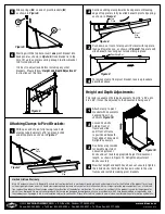
Slide springs (
K
) on end of pivot brackets (
E
)
as shown in
Figure 5
.
With open end of pivot clip facing rack, hold
clamp at approximately a 15° angle and slide
under top plate, as shown in
Figure 7
.
Starting with the top hole, insert
one
pivot bracket into
back panel as shown in
Figure 6
. Once bracket is in top
hole, lift up to compress spring enough to allow bracket
to fit into bottom hole.
It is best to adjust rack before installing any other
brackets. Please follow “
Height and Depth Adjustment
”
instructions at this time.
5
1
6
Continue sliding clamp towards back panel until leading
edge of top plate is fully inserted beneath pivot clip spring,
as shown in
Figure 8
.
Push down on front of clamp until it’s level with top plate,
then pull towards you, as shown in
Figure 9
. Top plate will
slide beneath rear wing nut to lock clamp in place.
To remove clamp from pivot bracket, reverse procedure
described above.
2
3
4
Figure 5
Attaching Clamps to Pivot Brackets:
Figure 6
Figure 7
Figure 9
Height and Depth Adjustments:
Attach clamp to pivot
bracket with documents
hanging from it, as
shown in
Figure 10
.
Loosen hex bolts
holding front U
frame and slide
until front of frame
is positioned beneath
front edge of document.
Retighten securely.
Five holes are provided
for height adjustment.
Loosen adjustment
knobs and set rack to appropriate height for document
length, as shown in Figure 10. Retighten adjustment
knobs securely.
Now that height and depth have been set, securely tighten
the 4 Allen bolts that hold the back crossbar to the side
frames and install remaining pivot brackets.
This rack is capable of holding documents from 18" x 24" up to
36" x 48". It must be adjusted to the documents being used.
1
2
3
4
Figure 10
x12
K
x12
E
Figure 8
Top
Plate
Top
Plate
Rear Wing Nut
Pivot
Clip
Pivot
Clip
Spring


