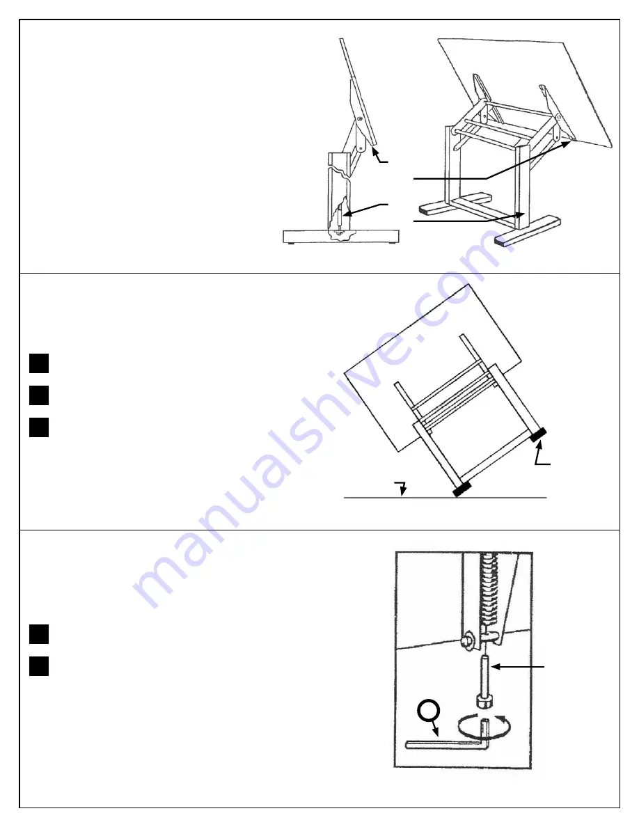
Release brake lever on right side of table. This allows both
springs to return to their natural, relaxed positions.
Using the Allen wrench provided (
G
, 5mm), tighten the Tilt
Adjustment Bolt to increase the tilt strength or loosen the
Tilt Adjustment Bolt to reduce the tilt strength as shown in
Figure 11
. This procedure will take some trial and error to
reach the desired spring tension.
The tabletop should tilt gently from the horizontal position
to the near-vertical position when the brake lever is released.
If it tilts too quickly or fails to tilt completely, adjust the Tilt
Control Spring as follows.
1
2
Tilt-Strength Adjustment
Figure 11
3
©2012 Alvin & CompAny, inC.
Release brake lever on right side of table. This allows both
springs to return to their natural, relaxed positions.
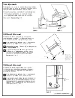
Elevate the left foot to gain access to the Lift Adjustment Nut
as shown in
Figure 10
.
Using the wrench provided (
F
, 17mm), tighten the Lift
Adjustment Nut to increase the lift strength or loosen
the Lift Adjustment Nut to reduce the lift strength. This
procedure will take some trial and error to reach the
desired spring tension.
The tabletop should rise gently to its uppermost position
when the brake lever is released. If it rises too quickly or fails
to rise completely, adjust the Lift Control Spring as follows.
1
2
3
Lift-Strength Adjustment
Figure 10
The Ensign table is designed to accommodate a variety of tabletop
sizes and weights. For best results, it is likely you will have to make
spring and tension adjustments before using your table.
There are 2 springs that control the functions of the Ensign table:
1. The spring inside the left leg controls the lift strength
2. The spring under the tabletop controls the tilt strength
Please refer to
Figure 8
and
Figure 9
.
Table Adjustments
Figure 8
Figure 9
Tilt
Control
Spring
Tilt
Adjustment
Bolt
Lift
Control
Spring
Position table as
shown to reach
adjustment nut
on bottom of Lift
Control Spring
(under foot)
Floor
G

