Please save these instructions for future reference
©2012 Alvin & CompAny, inC. • P.O. Box 188, Windsor, CT 06095-0722
Phone: 860-243-8991 • Toll-Free: 800-444-2584 • Fax: 860-242-8037 • Toll-Free Fax: 800-777-2896
www.alvinco.com
LIT-A12112 7/12
4
©2012 Alvin & CompAny, inC.
ENSIGN MODELS
31" x 42"
36" x 48"
EN42-3
EN42-4
EN48-3
EN48-4
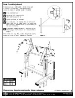
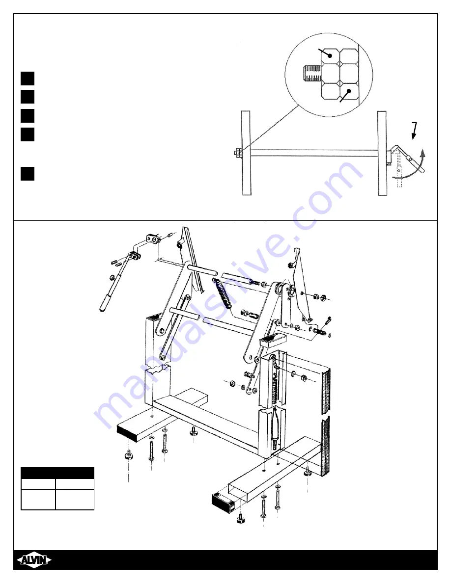
Figure 12
Release the brake lever
Loosen the outer nut, A, a few turns.
(No need to remove all the way)
Tighten inner nut, B, one revolution
Return brake lever to the locked position and test to see if
tabletop holds firmly in desired position. If not, release brake
and tighten nut B additional revolution(s). This procedure will
take some trial and error.
Once desired brake-locking strength is reached, tighten nut
A firmly up against nut B. Use care not to rotate nut B while
doing so.
The brake lever should hold the tabletop firmly at any height
or tilt position. If it fails to do so, follow this procedure to
increase the braking strength. Please refer to
Figure 12
.
1
2
3
4
5
Brake Control Adjustment
After extended table usage, the brake-lock strength will gradually
diminish and it will be necessary to repeat this procedure.
A
B
Brake
Lever

