4. Assembly Steps – Mechanism Parts
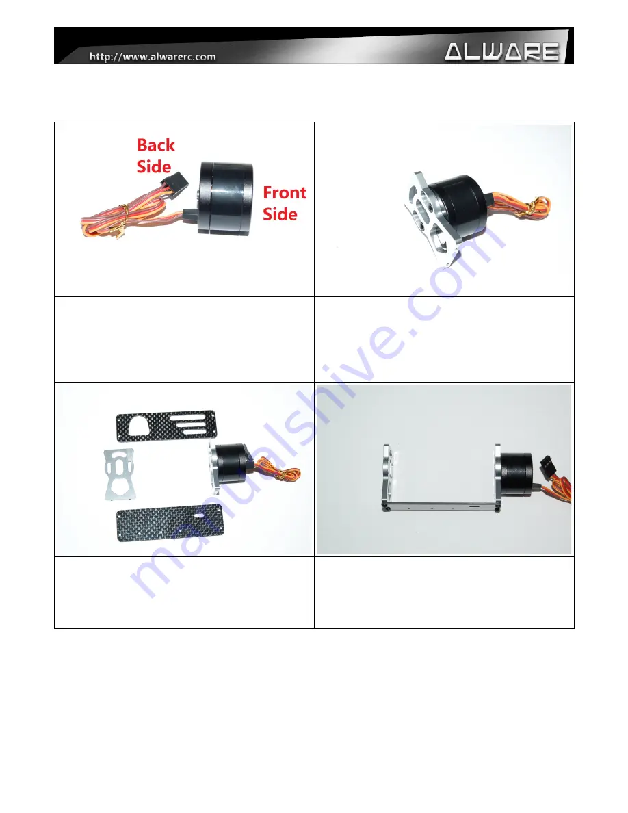
Step 1.
Recognization of BL Gimbal Motor oriantation.
Step 2.
Install a Stand Frame Mount onto the Front Side of BL
Gimbal Motor using M2.5x6mm Hex Cap Screws.
This is the Tilt Axis.
(Apply little amount of Thread Locker when securing
screw to metal parts.)
Step 3.
Prepare 1x Bottom Stand Plate, 1x Top Stand Plate, 1x
Stand Frame Mount and the Assembly from Step 2.
Sep 4.
Install the Bottom Stand Plate with two Stand Frame
Mounts using 4x M2x6mm Hex Cap Screws.
(Apply little amount of Thread Locker when securing
screw to metal parts.)
Page 6 of 16


