background image

Always 

O

n UPS Systems 


IMPORTANT SAFETY INSTRUCTIONS 


THIS MANUAL CONTAINS IMPORTANT INSTRUCTIONS THAT SHOULD BE 
FOLLOWED DURING INSTALLATION AND MAINTENANCE OF THE UPS AND 
BATTERIES. 


THE UPS SYSTEM IS NOT INTENDED FOR EXTERNAL USE UNLESS 
SPECIFICALLY DESIGNED FOR IT. 


ALL SERVICING MUST BE DONE BY QUALIFIED PERSONNEL.  DO NOT 
ATTEMPT TO SERVICE THIS EQUIPMENT YOURSELF.  OPENING OR 
REMOVING COVERS WILL RISK EXPOSURE TO DANGEROUS VOLTAGES. DO 
NOT LOCATE UPS IN AN AREA WHERE UNAUTORIZED PERSONNEL HAVE 
ACCESS. 


THE POWER SUPPLY FOR THIS UNIT MUST BE SINGLE PHASE RATED IN 
ACCORDANCE WITH THE EQUIPMENT DATA PLATE.  IT MUST BE SUITABLY 
GROUNDED. 


DO NOT STAND BEVERAGE CONTAINERS ON THE UNIT. 


EXTERNAL VENTING AND OPENINGS IN THE CABINET ARE PROVIDED FOR 
VENTILATION.  TO ENSURE RELIABLE OPERATION OF THE PRODUCT AND 
TO PROTECT FROM OVERHEATING, THESE OPENINGS MUST NOT BE 
BLOCKED OR COVERED.  OBJECTS MUST NEVER BE INSERTED INTO 
VENTILATION HOLES OR OPENINGS. 


THE POWER TERMINAL BLOCK ON THE UPS DISTRIBUTION PANEL WILL BE 
LIVE WHEN THE UNIT’S POWER SWITCH IS ON, WHETHER OR NOT THE 
UNIT AC SUPPLY IS PRESENT. 


QUALIFIED PERSONNEL SHOULD BE CONSULTED WHEN: 
1.


LIQUID HAS BEEN SPILLED INTO THE UNIT 

2.


THE UNIT DOES NOT OPERATE NORMALLY EVEN THOUGH THE 
OPERATING INSTRUCTIONS HAVE BEEN FOLLOWED 


DO NOT PLACE MAGNETIC STORAGE MEDIA ON TOP OF THE UNIT, AS THIS 
CAN RESULT IN DATA CORRUPTION. 


THIS UPS WAS DESIGNED TO POWER LOADS TYPICALLY FOUND IN MOST 
MODERN MICROPROCESSOR CONTROLLED EQUIPMENT.  DO NOT USE IT 
FOR PURE INDUCTIVE OR CAPACITIVE LOADS.  IT IS NOT RATED TO POWER 
LIFE SUPPORT EQUIPMENT. 


CAUTION: 

ALL RECORDED MEDIA, SUCH AS DISKETTES, TAPES AND CARTRIDGES, 
SHOULD BE KEPT A MINIMUM OF 60CM FROM THE UPS.  THE MAGNETIC 
FIELD CREATED BY OPERATION OF THE UPS MAY ERASE DATA ON THOSE 
DEVICES. 


ATTENTION: 

INSTALL THE ON-LINE UPS IN A VENTILATED AREA, AWAY FROM 
FLAMMABLE LIQUIDS, GASES, OR EXPLOSIVES.  DO NOT LET THE UNIT COME 
INTO CONTACT WITH WATER.  POTENTIALLY LETHAL VOLTAGES EXIST 
WITHIN THIS UNIT AS LONG AS THE BATTERIES ARE CONNECTED.  DO NOT 
TOUCH ELECTRICAL CIRCUITS WHEN POWER IS CONNECTED TO THE UPS.  
TURN THE UPS “OFF” AND DISCONNECT THE UNIT FROM THE POWER SOURCE 
BEFORE REMOVING THE COVER PLATES. 
ALL REPAIRS SHOULD BE PERFORMED BY QUALIFIED SERVICE PERSONNEL.  
READ THIS MANUAL CAREFULLY BEFORE INSTALLING OR USING THE UNIT.  
FOLLOW ALL PROCEDURES, AS DESCRIBED, TO INSURE SAFE, RELIABLE 
OPERATION OF THE UPS.


SAVE THESE INSTRUCTIONS 

M0301_N_Series_DM_Manual V1.4 2012-06-12 

ii 

Summary of Contents for GES-102NDM

Page 1: ...SLIMLINE DOORMOUNT UPS For Traffic Applications GES 102NDM GES 152NDM On Line 1kVA 1 5kVA Operators Manual M0301_N_Series_DM_Manual V1 4 2012 06 12...

Page 2: ...M0301_N_Series_DM_Manual V1 4 2012 06 12 THIS PAGE IS INTENTIONALLY BLANK...

Page 3: ...oid all warranties and may void UL cUL CSA listing Unauthorized modifications also can result in personal injury death or destruction or the equipment Uninterruptible Power Supply Uninterruptible Powe...

Page 4: ...NSULTED WHEN 1 LIQUID HAS BEEN SPILLED INTO THE UNIT 2 THE UNIT DOES NOT OPERATE NORMALLY EVEN THOUGH THE OPERATING INSTRUCTIONS HAVE BEEN FOLLOWED DO NOT PLACE MAGNETIC STORAGE MEDIA ON TOP OF THE UN...

Page 5: ...UNIT IS LEAKING LIQUID OR IF A WHITE POWDERY RESIDUE IS PRESENT BATTERIES MAY CONTAIN METALS AND OTHER CHEMICAL HAZARDOUS WASTE FOR PROPER DISPOSAL CONSULT YOUR LOCAL STATE AND FEDERAL EPA AND OTHER E...

Page 6: ...SPLAY 12 6 2 UPS METERING DISPLAY 12 6 3 BUTTON OPERATION 13 6 4 CONTROL PANEL FUNCTIONS 13 6 5 UPS CONFIGURATIONS 13 7 0 AUDIBLE ALARM 16 7 1 BACKUP MODE 16 7 2 LOW BATTERY 16 7 3 BYPASS 16 7 4 FAULT...

Page 7: ...supplied by the UPS Inverter The input Rectifier derives power from a utility AC source and supplies power to the Inverter while simultaneously float charging the storage batteries Back Up Upon failu...

Page 8: ...rue sine wave Thus it may be used to protect your loads from any power fluctuations e g blackouts brownouts over voltage conditions The UPS will supply a sufficient amount of steady constant AC power...

Page 9: ...tery system and raises the DC voltage to the DC Bus operating voltage for the inverter This allows the inverter to operate continuously at its optimum efficiency and voltage thus increasing reliabilit...

Page 10: ...maximizes efficiency and reduces power consumption Alternating between bypass and on line modes is achieved automatically and in accordance with the conditions of the AC supply power On line mode may...

Page 11: ..._N_Series_DM_Manual V1 4 2012 06 12 5 Other than during the initial 24 hours after startup or while the UPS is in charging mode diagnostic tests please see chapter 6 5 can be performed manually from t...

Page 12: ...mage or anything is missing contact the dealer from whom you purchased the unit and save the packaging for future shipment When the unit has passed the initial inspection record the installation date...

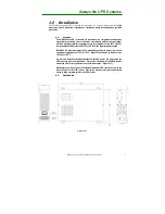
Page 13: ...room at an ambient temperature of 15 C to 25 C Battery life decreases by half for every 10 C above 25 C IMPORTANT Maximum battery life is obtained by placing the battery in a room at an ambient temper...

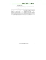
Page 14: ...anel Breaker Size Input Output Voltage Current Voltage Current 1000VA 700W 1000VA 110 50 60 15A 80 138Vac 12A max 120V 8 3A 1000VA 700W 1000VA 220 50 60 15A 160 276Vac 6A max 208 220 4 8A 4 55A 1500VA...

Page 15: ...UPS system Cables have been provided with the battery package for connection to the UPS system The 1000VA and 1500VA unit both use 36VDC battery systems A minimal battery system uses three 3 12VDC nom...

Page 16: ...s should be observed when working on batteries Remove watches rings and other metal objects Use tools with insulated handles Wear rubber gloves and boots Do not lay tools or metal parts on top of batt...

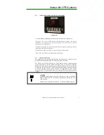
Page 17: ...FF button located on the front panel for at least three seconds The UPS should now start its self test testing the internal functions main synchronization and inverter startup After a successful test...

Page 18: ...O P VOLT V Shows Output AC voltage O P FREQ Hz Shows Output Frequency I P VOLT V Shows Input AC Voltage I P FREQ Hz Shows Input Frequency BAT VOLT V Shows Battery Voltage O P Load Shows of Maximum Rat...

Page 19: ...ction d Push the FUNC button to choose other function e Push the ENTER button to enable your function f Push the ENTER button to confirm and enable the selected function g If nothing has been pressed...

Page 20: ...ther confirm or save your selection Other options are saved and started automatically See Table 6 5 1 for further details 6 If no buttons are pressed for 10 seconds the UPS shall exit the configuratio...

Page 21: ...o bypass when unsynchronized Enable Disable Disable HE Mode Setting HE Mode Set Select if UPS runs in efficiency optimizer mode ON OFF OFF Frequency Conversion Freq Conv Setting Allows the UPS to outp...

Page 22: ...charge level of the batteries will be maintained automatically Under normal operating conditions the supplied batteries are expected to last approximately five 5 years or 200 discharges from date of...

Page 23: ...nstallation If used in conjunction with a status module the status module will have to be disconnected from the UPS Other advanced power protection solutions such as SNMP are provided by your dealer 1...

Page 24: ...n the USA at all times Using cables of improper size may damage your equipment and cause fire hazards Ground the UPS and the load equipment to a common point to prevent looping 1 Batteries should be i...

Page 25: ...ement product that uses multiple open standards such as Telnet HTTP and SNMP to provide full management of supported devices The SNMP Adapter is designed to connect directly to the network and allow f...

Page 26: ...1 second Output signal pin assignment Fault Pin 1 2 3 On Battery Pin 4 5 6 Battery Low Pin 7 8 On Bypass Pin 9 10 On Inverter Pin 11 12 M0301_N_Series_DM_Manual V1 4 2012 06 12 20 Dry Contact Capacity...

Page 27: ...er Charge Constant Beep Batteries are over charged Turn off protected loads Turn off UPS and call local dealer Low Battery 2 beeps every 5 seconds The unit is operating on Battery Power and will shutd...

Page 28: ...YES Via No 30 to 60 C Extended r Common LCD LED Status Depends Auto Self test Temperat Battery Bank 4 1 125 for 1 Sealed Lead Acid Mainte CONFORMANCE PROTECTION BATTERY External OUTPUT GENERAL INPUT...

Page 29: ...775 Email sales alwayson com Website www alwayson com 13 2 QA Warranty Questions Always On UPS Systems Inc Bldg 1 150 Campion Road Kelowna BC Canada V1X 7S8 Phone 250 491 9777 Ext 209 Fax 250 491 9775...

Reviews: