Timekeeper™
Users Manual
01/11/20
Remote time of day setting
When the time of day is being set, the TME command is generated when the time set mode is exited. This is useful
when setting the time of day in the remote displays. When multiple timers and/or displays are connected together, the
time of day information is automatically passed from the controlling unit to all the slave units.
It may be desirable for the remote units to display the time of day when not being used for other purposes.
To cause the remote units to remain in the time of day clock mode while the controller is disconnected from the system,
perform the following steps.
●
Make sure the time of day clock is set correctly.
●
Press the clock button to cause the time of day to appear in the display.
●
Disconnect the controlling unit from the system.
●
All the remote displays will display the time of day.
To cause the remote units to go dark while the controller is disconnected from the system, perform the following steps.
●
Press the reset button to cause the timer or counter to appear in the display.
●
Disconnect the controlling unit from the system.
●
All the remote displays will display go dark after a few seconds.
Technical Description
This section contains information that might be useful for system designers, system integrators and installers.
Power up
When the unit is first powered up all the LEDs come on and the scrolling message "Hello” appears in the display.
NOTE: If the “Hello” message appears, but does not scroll, the firmware is a variation not described by this manual.
NOTE: If you have stored a power up preset, the Hello message will not appear.
Connectors
The Timerkeeper
TM
unit will have some or all of the following connectors. Refer to the data sheet for the specific model
for details.
•
RJ11 serial data connectors.
•
RJ11 ground closure input connector.
•
RJ45 serial data connectors.
•
Power Connector
RJ11 Serial Data Connectors
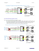
RJ11 accessory connectors:
•
RJ11 Receive Jack, marked “RX” or “IN”. This connector receives data from other units on DATA 1 and
transmits data on DATA 3.
•
RJ11 Transmit Jack, marked “TX” or “OUT”. This connector transmits data to other units on DATA 1 and
receives data on DATA 3.
•
The DATA 2 pin on the and RJ11 carries the 50/60Hz sync signal.
•
Using a 4 conductor modular cord, the RJ11-TX connector is typically used for transmit data. RJ11-RX
connector is typically used for receive data.
•
Using a 6 conductor modular cord, the RJ11-TX is typically used for transmit data on DATA 1 and receive
data on DATA 3. The RJ11-RX connector is typically used for receive data on DATA 1 and transmit data on
DATA 3.
VERSION=5C
Page 27 of 33


