Timekeeper™
Users Manual
01/11/20
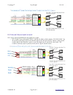
RJ11 Ground Closure Input Connector
RJ11 remote control timer RSSR jack with ground closure inputs:
•
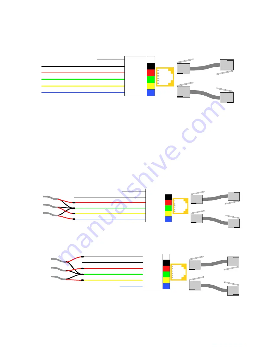
RJ11 Ground Closure Jack, marked “RSSR”, with lines described in this document as “IN1,IN2,IN3,IN4”. See
the connection diagram provided in the installation instructions for a particular unit. Buttons, readers, optical
couplers, photo beams, hall-effect sensors, or more line outputs may be connected to these inputs. This
connector also has an output to provide external power to operate external sensors.
VERSION=5C
Page 28 of 33
with Timekeeper
TM
Display
(1) WH
(2) BK
(4) GN
(5) YL
(6) BL
(3) RD
Use 6P6C Crossover Modular Cord
Use 6P6C Standard Modular Cord
with LED displays.
IN 3
+12V
IN 4
IN 1
Ground
IN 2
RJ-14
Reset
Pause
Run/Lap
Timer Run/Lap
+12V
Timer Pause
Ground
Timer Reset
—
Timekeeper
TM
Remote Ground Closure Inputs Setup as a Counter
with Timekeeper
TM
Display
(1) WH
(2) BK
(4) GN
(5) YL
(6) BL
(3) RD
Use 6P6C Crossover Modular Cord
Use 6P6C Standard Modular Cord
with LED displays.
IN 3
+12V
IN 4
IN 1
Ground
IN 2
RJ-14
—
+12V
Counter Decrement
Ground
Counter Reset
Counter Increment
Incr
Reset
Decr
Timekeeper
TM
Serial Data Input and Output on the RJ11 jacks
with Timekeeper
TM
Display
(1) WH
(2) BK
(4) GN
(5) YL
(6) BL
(3) RD
Use 6P6C Crossover Modular Cord
Use 6P6C Standard Modular Cord
with LED displays.
Data 3
+12V
Data 4
Data 1
Ground
Data 2
RJ-14
—
+12V
RX
Ground
60 Hz Sync
TX
—
+12V
TX
Ground
60 Hz Sync
RX


