Timekeeper™
Users Manual
01/11/20
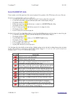
Front panel Led definitions – TMR017, TMR221 and TMR106B models only
Lower Left side
ON=Beep on
OFF=Beep off
Middle Left side
ON=Count up
OFF=Count down
Upper Left Side
ON=PM
OFF=AM
Lower Right side
ON=RED indicator,
Time is up
Middle Right Side
ON=YEL indicator,
Yellow warning (“Wrap-
it-up” time)
Upper Right Side
ON=GRN indicator,
Time is running
Above Clock Button
RED=Time set mode,
GRN=No sync signal,
BLINKING
GRN=SYNC**
**NOTE: See section on SYNC for more details.
Dimming the display
Not supported on all models. The dimmer value in the range 0 to 99 provides several distinct brightnesses, where 0-3 is
the lowest brightness, and 96-99 is the highest brightness.
Note: Some models have 25 distinct levels while other models have only 4 or 10 distinct brightness levels.
Remote Ground Closure Inputs
The remote ground closure inputs are user configurable. The default functions for these inputs
are described here. See the MSETUP configuration setting parameter for alternate functions for
these inputs.
The timer can be started, stopped or reset by remote control. Grounding the respective signal
activates the function. Typically the signals are grounded by pressing buttons on remote units.
Notice that inputs IN2 and IN3 are dual function. They operate differently depending on whether
the display is in timer mode or Tallye mode:
•
IN1 – Changes the display to timer mode. Starts the timer.
•
IN2 – In timer mode, stops the timer.
•
IN2 – In Tallye mode, decrements the tally count by the scale factor (default 1).
•
IN3 – In timer mode, resets the timer values to the initial preset values.
•
IN3 – In Tallye mode, sets the tally count to zero. Reset does not stop the timer.
•
IN4 – Changes the display to Tallye mode. Increments the tally count by the scale
factor (default 1).
The KP03A or OC002A keypads can be configured to use the inputs you specify. Remove the
rear cover of the KP03A or OC002A and configure the jumpers the way you desire.
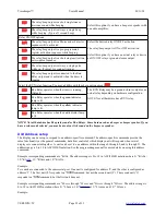
Common configurations.
VERSION=5C
Page 8 of 33


