TM 9-2320-283-20-3
STEERING SYSTEM.
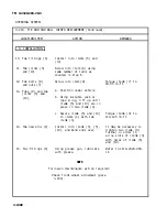
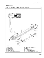
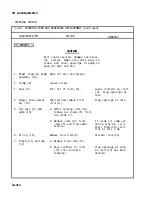
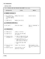
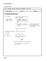
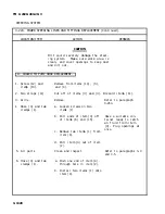
3-218. TIE ROD AND BALL JOINTS REPLACEMENT (Continued).
LOCATION/ITEM
ACTION
REMARKS
C. INSTALLATION.
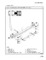
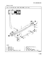
10. Two fittings (6).
Install into items (5) and
(10).
11. Two joints (5)
Screw into item (9) using
and (10).
same number of turns as
counted in step 6.
12. Two bolts (8)
Screw into item (9).
Torque items (7) to
and nuts (7).
40-55 lb-ft.
13. Tube (9) and two
a. Position under vehicle.
joints (5) and
(10).
b. Using suitable jack or
rope sling, lift up until
items (5) and (10) are in
place in two items (4).
c. Secure items (5) and (10)
Torque items (3) to
to items (4) with two
110-125 lb-ft.
items (3).
14. Two new pins (2).
Install into items (3), (5),
(10), and bend ends over.
It may be necessary to
tighten two items (3)
further in order to
aline slots of items (3)
with holes of items (5)
and (10).
15. Two fittings (6).
Using grease gun, lubricate
Refer to LO 9-2320-283-
with grease.
12.
NOTE
Follow-on maintenance action required:
Check front wheel alinement (para
3-203).
3-1308
Summary of Contents for M915A1
Page 10: ......
Page 17: ......
Page 59: ......
Page 130: ......
Page 155: ......
Page 378: ...TM 9 2320 283 20 3 CAB AND BODY 3 264 OUTSIDE FRONT HANDLE REPLACEMENT Continued 3 1551...
Page 622: ...TM 9 2320 283 20 3 GAGES NONELECTRICAL 3 309 TACHOGRAPH REPLACEMENT Continued TA 237846 3 1795...
Page 669: ......
Page 673: ......
Page 705: ......
Page 707: ......
Page 717: ......
Page 737: ......
Page 738: ......
Page 739: ......
Page 740: ......
Page 741: ......
Page 742: ......
Page 743: ......
Page 744: ......
Page 745: ......
Page 746: ......
Page 748: ......
Page 756: ...PIN 054576 000...


