TM 9-2320-283-20-3
WHEELS.
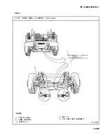
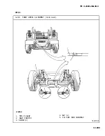
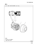
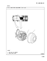
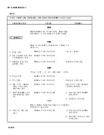
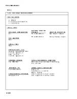
3-203. FRONT WHEEL ALINEMENT (Continued).
LOCATION/ITEM
ACTION
REMARKS
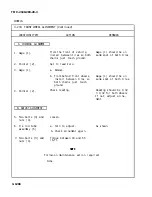
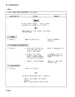
A. CHECKING ALINEMENT.
1. Gage (1).
From the front of vehicle,
Gage (1) should be on
install between tires so both
same spot of both tires.
chains just touch ground.
2. Pointer (2).
Set to read zero.
3. Gage (1).
a. Remove.
b. From behind front wheels,
Gage (1) should be on
install between tires so
same spot of both tires.
both chains just touch
ground.
4. Pointer (2).
Check reading.
Reading should be 1/32
± 1/32 for both wheels.
If not, adjust aline-
ment.
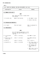
B. ADJUST ALINEMENT.
5. Two bolts (3) and
Loosen.
nuts (4).
6. Tie rod tube
a. Turn to adjust.
As shown.
assembly (5).
b. Check alinement again.
7. Two bolts (3) and
Torque between 40 and 55
nuts (4).
lb-ft.
NOTE
Follow-on maintenance action required:
None.
3-1208
Summary of Contents for M915A1
Page 10: ......
Page 17: ......
Page 59: ......
Page 130: ......
Page 155: ......
Page 378: ...TM 9 2320 283 20 3 CAB AND BODY 3 264 OUTSIDE FRONT HANDLE REPLACEMENT Continued 3 1551...
Page 622: ...TM 9 2320 283 20 3 GAGES NONELECTRICAL 3 309 TACHOGRAPH REPLACEMENT Continued TA 237846 3 1795...
Page 669: ......
Page 673: ......
Page 705: ......
Page 707: ......
Page 717: ......
Page 737: ......
Page 738: ......
Page 739: ......
Page 740: ......
Page 741: ......
Page 742: ......
Page 743: ......
Page 744: ......
Page 745: ......
Page 746: ......
Page 748: ......
Page 756: ...PIN 054576 000...


