TM 9-2320-283-20-3
CAB AND BODY.
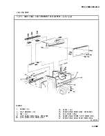
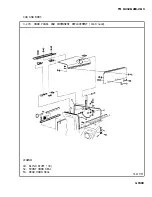
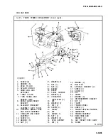
3-271. FRONT FENDER REPLACEMENT (Continued).
LOCATION/ITEM
ACTION
REMARKS
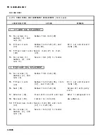
46. Support (32).
Aline with mounting holes in
side of item (44). Secure
with three items (29) and
(43).
47. Bracket (42).
Aline with mounting holes in
side of item (44). Secure
with item (39).
48. Support (20).
Aline and install. Secure
with four items (26) and
(17).
49. Three insulators
(22) l
Install into item (20).
50. Brace (19).
Aline and install. Secure
with items (18), (28), (27),
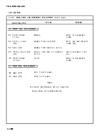
51. Two screws (37),
Loosen and remove from item
four washers (34),
Inspect item (35) and
and two nuts (33).
item (35) and two items (36). two items (36) for
serviceability. Replace
if damaged.
52. Two screws (37),
Install into two items (36)
four washers (34), and item (35). Tighten two
and two nuts (33). items (33).
NOTE
Follow-on maintenance action required:
Install brush guard brace (para
3-236).
Close and latch hood (TM 9-2320-
283-10).
3-1610
Summary of Contents for M915A1
Page 10: ......
Page 17: ......
Page 59: ......
Page 130: ......
Page 155: ......
Page 378: ...TM 9 2320 283 20 3 CAB AND BODY 3 264 OUTSIDE FRONT HANDLE REPLACEMENT Continued 3 1551...
Page 622: ...TM 9 2320 283 20 3 GAGES NONELECTRICAL 3 309 TACHOGRAPH REPLACEMENT Continued TA 237846 3 1795...
Page 669: ......
Page 673: ......
Page 705: ......
Page 707: ......
Page 717: ......
Page 737: ......
Page 738: ......
Page 739: ......
Page 740: ......
Page 741: ......
Page 742: ......
Page 743: ......
Page 744: ......
Page 745: ......
Page 746: ......
Page 748: ......
Page 756: ...PIN 054576 000...

