TM 9-2320-283-20-3
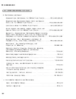
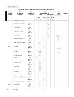
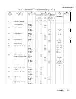
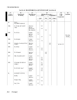
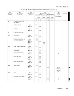
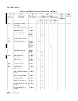
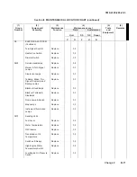
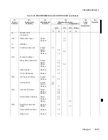
Section II. MAINTENANCE ALLOCATION CHART (continued)
(4)
Maintenance Level
Field Sustainment
Unit
DS
GS
Depot
(1)
Group
Number
(2)
Component/
Assembly
(3)
Maintenance
Function
C
O
F
H
D
(5)
Tools
and
Equipment
(6)
Remarks
05 COOLING
SYSTEM
(Continued)
Water Pump Idler Pulley
Replace
0.5
Crankshaft
Pulley
Replace
0.1
Accessory
Drive
Belts
Inspect
Adjust
Replace
0.2
0.2
1.0
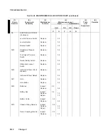
06 ELECTRICAL
SYSTEM
0601
Alternator & Regulator
Inspect
Replace
Adjust
(Internal)
Test
Repair
0.2
1.0
0.5
0.5
2.0
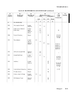
Alternator Drive Belts
Inspect
Adjust
Replace
0.1
0.1
0.3
0603
Starter Motor and
Solenoid
Replace
Repair
0.9
1.8
Starter
Relay
Inspect
Replace
0.1
0.5
0607 Instrument
Gages
Replace
0.5
0608 Ignition
Switch
Replace
0.5
Start
Switch
Replace
0.5
Ether Quick-Start Button
Switch
Replace 0.5
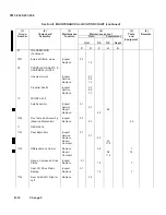
Clearance Lamp Switch
Replace
0.5
Headlamp Switch
Replace
0.5
Blackout Toggle Switch
Replace
0.5
Engine Retarder Selector
Switch
Replace
0.5
Engine Retarder Foot
Switch
Replace 0.5
B-10
Change 2
Summary of Contents for M915A1
Page 10: ......
Page 17: ......
Page 59: ......
Page 130: ......
Page 155: ......
Page 378: ...TM 9 2320 283 20 3 CAB AND BODY 3 264 OUTSIDE FRONT HANDLE REPLACEMENT Continued 3 1551...
Page 622: ...TM 9 2320 283 20 3 GAGES NONELECTRICAL 3 309 TACHOGRAPH REPLACEMENT Continued TA 237846 3 1795...
Page 669: ......
Page 673: ......
Page 705: ......
Page 707: ......
Page 717: ......
Page 737: ......
Page 738: ......
Page 739: ......
Page 740: ......
Page 741: ......
Page 742: ......
Page 743: ......
Page 744: ......
Page 745: ......
Page 746: ......
Page 748: ......
Page 756: ...PIN 054576 000...


