CHAPTER 4: MAINTENANCE
THIN-LINE
®
SERIES 180M WELD HEADS
4-2
990-133
Section III. Tare Spring Adjustment
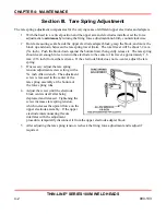
The tare spring adjustment compensates for the varying mass of different upper electrodes and adapters.
1
With the head in a vertical position and the upper arm and electrodes installed, set the force
adjustment to
minimum
by turning the firing force adjustment knob fully counterclockwise.
2
Hold a measuring scale beside the upper electrode adapter block, grasp the block, and move the
block up and down between the tare spring travel limits. The total travel will be about 3.2 mm
(
⅛
inch). Push the block down against the bottom limit, then gently release it. The tare spring
should exert enough force to return the electrode to the center of its travel, approximately 1.6
mm (1/16 inch) from either extreme. If the electrode block does not re-center, adjust the tare
spring.
3
If necessary, adjust the tare spring
tension adjustment screw setting with a
⅛
inch Allen wrench. The adjustment
screw is recessed in the center of the
tare spring assembly at the bottom of
the force spring tube.
4
Adjust the screw until the electrode
block centers itself after being
depressed and released. Tightening the
screw increases tare spring tension,
which increases the upward force on the
upper electrode assembly. If the upper
electrode interconnecting flexure
interferes with the adjustment
procedure, temporarily disconnect it from the upper electrode adapter block.
5
After adjusting the tare spring tension, recheck the firing force adjustment and readjust if
required.
Summary of Contents for THIN-LINE 180 M Series
Page 1: ...990 133 REV F WELD HEAD THINLINE 180 M SERIES OPERATION MANUAL ...
Page 34: ......
Page 38: ......
Page 42: ......

