background image

Component Testing Procedures 


!

WARNING


To avoid risk of electrical shock, personal injury or death; disconnect power to oven before servicing, unless  
testing requires power. 

RT2310015   Rev. 0 


November 2001 


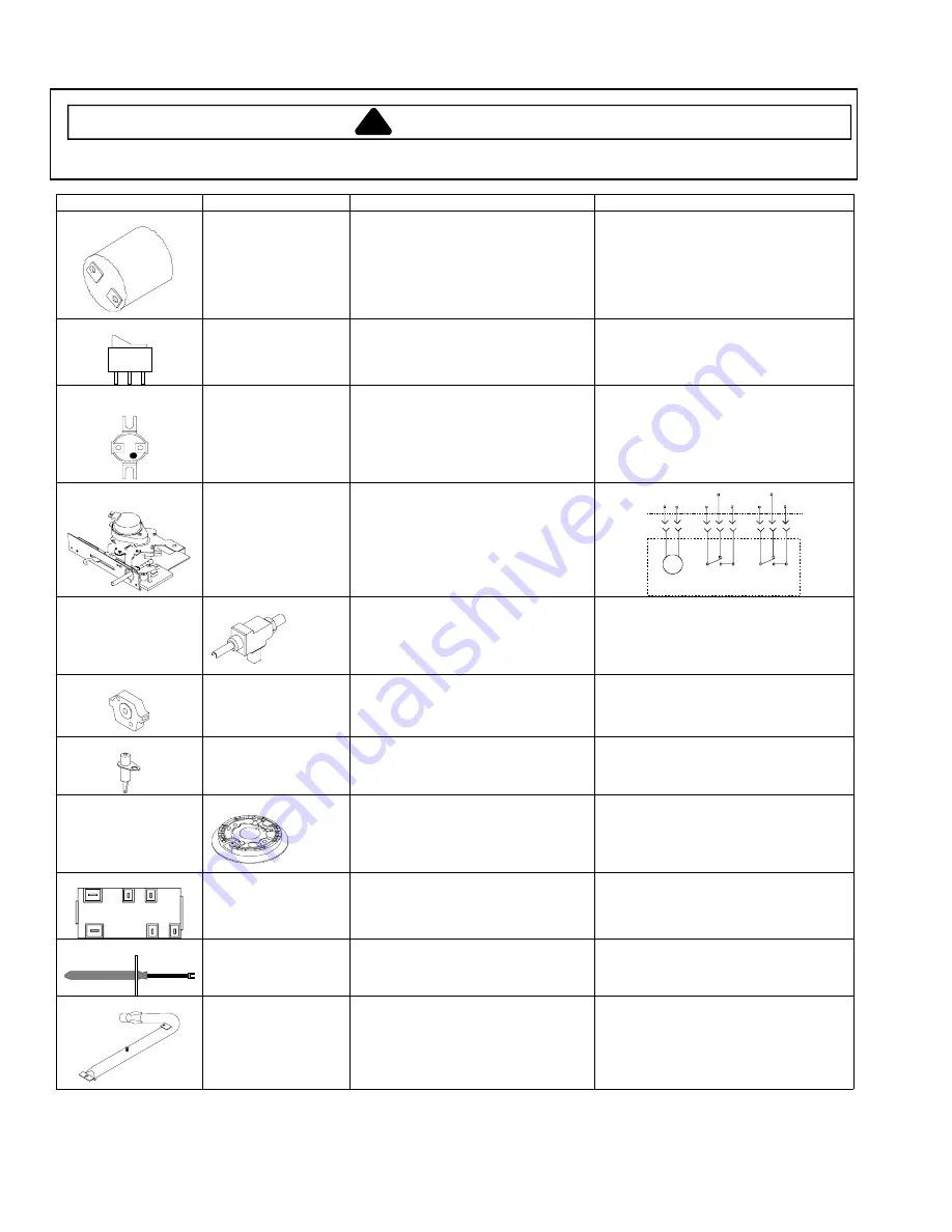
Illustration Component 

Test 

Procedure 

Results 

31823701 


Oven light socket 

Remove one wire from receptacle and 
test resistance of terminals..................  
 
Measure voltage at oven light ..............  

 
Indicates continuity with bulb screwed in. 
 
120 VAC, see wiring diagram for terminal 
identification. 
If no voltage is present at oven light, 
check wiring or light switches. 

31986601 


Rocker switch 

Measure continuity of switch positions: 

Closed..............................................  
Open ................................................  

 
Continuity, if not replace. 
Infinite, if not replace. 

31933003 
31933004


Limits Oven 

limit 

Closed..............................................  
Open ................................................  

Fan limit 

Closed..............................................  
Open ................................................  

See wiring diagram. 
210

°

240

°

 
155

°

115

°

31933401 


Autolatch assembly 
with door plunger 
switch 

Disconnect wires and test for 
continuity per diagram. 
 
Refer to Parts Manual for correct 
autolatch switch associated with the 
correct manufacturing number. 

M

120 VAC
  Motor

Lock/Unlock
     Switch

 Door
Switch

L1 L2

COM

NC

NO COM

NC

NO


0315960

 5 K btu 

0315961

 9 K btu 

0315962

 12 K btu 

270

°

 valve 


Verify gas is supplied. 
 
Orifice adjusted for Natural or LP.  
 
Adjust set screw for simmer control. 


0316572 


Spark 270

°

 switch 

Test for voltage at terminals ................  
 
Disconnect wiring and check for 
continuity in LITE position....................  

120 VAC 
 
 
Continuity in LITE position. 

0316773 


Spark ignition 
electrode 

Test for resistance of spark lead .........  
 
Test ignitor to chassis..........................  

Continuity 
 
No continuity from ignitor to chassis. 

0315769

 5 K btu 

0315768

 9 K btu 

0315767

 12 K btu 

Top surface burner 


Verify gas is supplied ..........................  
 
Verify burner cap is positioned 
correctly. 
 

Check for obstructions in burner ports. 

31962701 

L

A

B

A1

B1

N


Spark module 4 + 0 
 

Test for voltage at terminals L and N ...  
 
Check polarity and ground...................  

120 VAC 
 
See wiring diagram 

31968201 


Temperature sensor 

Measure resistances ...........................  
 

Approximately 1100 

 at room 

temperature 75

°

F. 

31716501 


Bake burner 

Verify gas is supplied. 
 
Orifice adjusted for Natural or LP ........  
 
Check for obstructions or 
contamination in ports .........................  

Set for Natural Gas from the factory 
 
Adjust as necessary. 
 
 
Replace if punctured or torn. 


Summary of Contents for ACS3350AB

Page 1: ... requires power Model ACS3350A Model ACS3350A Power Source Features Voltage rating 120 VAC One piece cast iron burner grates X Amperage rating 15 Amp Frameless glass door with window X Frequency 60 Hz Interior oven light X Water Column Pressure Two oven racks 5 positions X Natural 6 in W C P Removable full width storage drawer X LP Propane 10 in W C P Self cleaning porcelain oven X Surface Burner ...

Page 2: ...rect manufacturing number M 120 VAC Motor Lock Unlock Switch Door Switch L1 L2 COM NC NO COM NC NO 0315960 5 K btu 0315961 9 K btu 0315962 12 K btu 270 valve Verify gas is supplied Orifice adjusted for Natural or LP Adjust set screw for simmer control 0316572 Spark 270 switch Test for voltage at terminals Disconnect wiring and check for continuity in LITE position 120 VAC Continuity in LITE positi...

Page 3: ...alve with 120 VAC 0042303 Pressure regulator Verify gas pressure W C P If on LP service verify proper gas supply conversion 6 Natural 10 LP propane 0301361 H R A A G Shut off valve Check to verify gas supply is turned on Venturi Shutter settings Nominal Tol 125 1 8 031 1 32 308607 ERC cooling blower Verify supply voltage Check continuity of terminals and verify terminals are not shorted to chassis...

Page 4: ...to activate Activation of the pad will stop when the pad is released Bake Energizes bake element Broil Energizes broil element Stop Time Beeper ON and micro ID Timer No function Clock All display segments lite Cook Time Checksum and sensor temp Slew Pads Sequences through display segments Clean Door lock codes 3 lock and unlock contacts closed 2 lock closed unlock open 1 lock open unlock closed 0 ...

Page 5: ...wing or noisy reduce airflow to burner If burner flame is yellow and does not hold its shape increase airflow to burner Converting Surface Burners for Use with LP Propane 1 Remove 4 burner control knobs from range Exposes 2 screws on burner control panel 2 Remove 2 screws from burner control panel Panel drops slightly after screws are removed 3 Grasp bottom of burner control panel gently lift and ...

Page 6: ...ing Diagram and Schematic WARNING To avoid risk of electrical shock personal injury or death disconnect power to oven before servicing unless testing requires power RT2310015 Rev 0 November 2001 6 ACS3350A ...

Page 7: ...ing Diagram and Schematic WARNING To avoid risk of electrical shock personal injury or death disconnect power to oven before servicing unless testing requires power November 2001 RT2310015 Rev 0 7 ACS3350A ...

Page 8: ...Notes RT2310015 Rev 0 November 2001 8 ...

Reviews: