background image

5

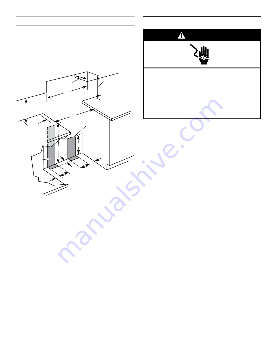
Cabinet Dimensions

Cabinet opening dimensions shown are for 25" (64.0 cm) 

countertop depth, 24" (61.0 cm) base cabinet depth and  

36" (91.4 cm) countertop height.
If the cabinet depth is greater than 24" (61.0 cm), oven frame 

must extend beyond cabinet fronts by ½" (1.3 cm) minimum.

IMPORTANT: 

If installing a range hood or microwave hood 

combination above the range, follow the range hood or 

microwave hood combination installation instructions for 

dimensional clearances above the cooktop surface.

A.  18" (45.7 cm) min. clearance upper side cabinet to countertop
B.  13" (33.0 cm) max. upper cabinet depth
C.  30" (76.2 cm) min. cabinet opening width
D.  For min. clearance to top of cooktop, see NOTE.*
E. 30¹⁄

8

" (76.5 cm) min. opening width

F.  This shaded area recommended for installation of electrical outlet.
G. This shaded area recommended for installation of rigid gas pipe.
H.  2" (5.1 cm) min. countertop space to side wall or other

  combustible material
I.  24" (61.0 cm)
J.  10" (25.4 cm)
K.  8" (20.3 cm)
L.  5" (12.7 cm)
M. 2" (5.1 cm)
N.  3" (7.6 cm)

 * 

NOTE: 

24" (61.0 cm) minimum when bottom of wood or 

metal cabinet is covered by not less than ¹⁄

4

" (0.64 cm) flame 

retardant millboard covered with not less than No. 28 MSG 

sheet steel, 0.015" (0.4 mm) stainless steel, 0.024" (0.6 mm) 

aluminum, or 0.020" (0.5 mm) copper.

   30" (76.2 cm) minimum clearance between the top of the 

cooking platform and the bottom of an uncovered wood or 

metal cabinet.

Electrical Requirements

IMPORTANT:

 The range must be electrically grounded in 

accordance with local codes and ordinances, or in the absence 

of local codes, with the National Electrical Code, ANSI/NFPA 70, 

latest edition.
If codes permit and a separate ground wire is used, it is 

recommended that a qualified electrical installer determine that 

the ground path is adequate.
A copy of the above code standards can be obtained from:

National Fire Protection Association

1 Batterymarch Park

Quincy, MA 02169-7471

CSA International

8501 East Pleasant Valley Road

Cleveland, OH 44131-5575


A 120 volt, 60 Hz., AC only, 15-amp fused, electrical circuit 

is required. A time-delay fuse or circuit breaker is also 

recommended. It is recommended that a separate circuit 

serving only this range be provided.


This range is equipped with a power supply cord having a   

3 prong ground plug. To minimize possible shock hazard,  

the cord must be plugged into a grounded 3 prong outlet.


Electronic ignition systems operate within wide voltage limits, 

but proper grounding and polarity are necessary. Check that 

the outlet provides 120-volt power and is correctly grounded.
This range is equipped with an electronic ignition system that 

will not operate if plugged into an outlet that is not properly 

polarized.


Performance of this range will not be affected if operated 

on a GFCI-protected electrical outlet. However, occasional 

nuisance tripping of the GFCI breaker is possible due to the 

normal operating nature of electronic gas ranges.


The wiring diagram is located on the back of the range in a 

clear plastic bag.

NOTE:

 The metal chassis of the range must be grounded in 

order for the control panel to work. If the metal chassis of the 

range is not grounded, no keypads will operate. Check with 

a qualified electrician if you are in doubt as to whether the 

metal chassis of the range is grounded.

A

B

C

D

E

F

G

H

J

K

M

L

L

N

I

Electrical Shock Hazard

Plug into a grounded 3 prong outlet.
Do not remove ground prong.
Do not use an adapter.
Do not use an extension cord.
Failure to follow these instructions can result in death, 
fire, or electrical shock.

WARNING

Summary of Contents for AGR4230BAW

Page 1: ...pack Range 7 Install Anti Tip Bracket 7 Make Gas Connection 8 Verify Anti Tip Bracket Is Installed and Engaged 9 Level Range 10 Electronic Ignition System 10 Complete Installation 11 GAS CONVERSIONS 12 LP Gas Conversion 12 Complete Conversion 14 Natural Gas Conversion 14 Complete Conversion 16 IMPORTANT Save for local inspector s use Installer Leave installation instructions with the homeowner Hom...

Page 2: ... property damage personal injury or death Do not store or use gasoline or other flammable vapors and liquids in the vicinity of this or any other appliance WHAT TO DO IF YOU SMELL GAS Do not try to light any appliance Do not touch any electrical switch Do not use any phone in your building Immediately call your gas supplier from a neighbor s phone Follow the gas supplier s instructions If you cann...

Page 3: ...ket to floor Parts needed Check local codes and consult gas supplier Check existing gas supply and electrical supply See Electrical Requirements and Gas Supply Requirements sections In the State of Massachusetts the following installation instructions apply Installations and repairs must be performed by a qualified or licensed contractor plumber or gasfitter qualified or licensed by the State of M...

Page 4: ...ectrical supply is required See Electrical Requirements section Proper gas supply connection must be available See Gas Supply Requirements section Contact a qualified floor covering installer to check that the floor covering can withstand at least 200 F 93 C Use an insulated pad or 0 64 cm plywood under range if installing range over carpeting IMPORTANT To avoid damage to your cabinets check with ...

Page 5: ...mended that a qualified electrical installer determine that the ground path is adequate A copy of the above code standards can be obtained from National Fire Protection Association 1 Batterymarch Park Quincy MA 02169 7471 CSA International 8501 East Pleasant Valley Road Cleveland OH 44131 5575 A 120 volt 60 Hz AC only 15 amp fused electrical circuit is required A time delay fuse or circuit breaker...

Page 6: ...ce connector If local codes permit a new CSA design certified 4 to 5 ft 122 to 152 4 cm long 1 3 cm or 1 9 cm I D flexible metal appliance connector may be used for connecting range to the gas supply line A 1 3 cm male pipe thread is needed for connection to the female pipe threads of the inlet to the appliance pressure regulator Do not kink or damage the flexible metal tubing when moving the rang...

Page 7: ... range to support the range when it is laid on its back 5 Using 2 or more people firmly grasp the range and gently lay it on its back on the cardboard corners 6 Pull cardboard bottom firmly to remove then remove foam support 7 Use an adjustable wrench to loosen the leveling legs Adjust the leveling legs to the correct height Leveling legs can be loosened to add up to a maximum of 1 2 5 cm A minimu...

Page 8: ...se with LP gas to the smaller thread ends of the flexible connector adapters see B and F in the following illustration 2 Attach 1 adapter to the gas pressure regulator and the other adapter to the gas shut off valve Tighten both adapters being certain not to move or turn the gas pressure regulator 3 Use a 15 16 2 4 cm combination wrench and an adjustable wrench to attach the flexible connector to ...

Page 9: ...the broiler and grasp the lower right or left side of the control panel as shown NOTE If your countertop is mounted with a backsplash it may be necessary to grasp the range higher than is shown in the illustration 2 Slowly attempt to tilt the range forward If you encounter immediate resistance the range foot is engaged in the anti tip bracket 3 If the rear of the range lifts more than 1 3 cm off t...

Page 10: ...p and oven burners use electronic igniters in place of standing pilots When the cooktop control knob is turned to the IGNITE position the system creates a spark to light the burner This sparking continues until the control knob is turned to the desired setting When the oven control is turned to the desired setting a hot surface igniter heats to a bright orange and ignites the gas No sparking occur...

Page 11: ...tter screw 8 Reinstall flame spreader and oven tray Reinstall the oven racks and close oven door 9 Close the broiler door Complete Installation 1 Check that all parts are now installed If there is an extra part go back through the steps to see which step was skipped 2 Check that you have all of your tools 3 Dispose of recycle all packaging materials 4 Check that the range is level See the Level Ra...

Page 12: ... International approved gas supply line Install a shut off valve Securely tighten all gas connections If connected to LP have a qualified person make sure gas pressure does not exceed 14 36 cm water column Examples of a qualified person include licensed heating personnel authorized gas company personnel and authorized service personnel Failure to do so can result in death explosion or fire WARNING...

Page 13: ...puds using a 7 mm combination wrench A Spud B Holder NOTE The range is equipped with 3 standard burners and 1 simmer burner right rear A Standard burner LP gas orifice spud number 88 B Standard burner LP gas orifice spud number 88 C Simmer burner LP gas orifice spud number 70 Yellow White D Standard burner LP gas orifice spud number 88 5 Place the Natural gas orifice spuds in the parts bag for fut...

Page 14: ...very distinct blue flame to 0 64 cm to 1 3 cm long The outer cone is not as distinct as the inner cone LP gas flames have a slightly yellow tip 4 Close the broiler door and turn the knob to OFF position 5 Refer to the Complete Installation section to complete this procedure Natural Gas Conversion 1 Turn manual shut off valve to the CLOSED position A Gas supply line B Manual shut off valve closed p...

Page 15: ...uds are stamped 149 and one is stamped 110 Red Brass 3 Remove the LP gas orifice spuds using a 7 mm combination wrench 4 Install the Natural gas orifice spuds using a 7 mm combination wrench A Spud B Holder NOTE The range is equipped with 3 standard burners and 1 simmer burner right rear A Standard burner Natural gas orifice spud number 149 B Standard burner Natural gas orifice spud number 149 C S...

Page 16: ...ntaining literature 7 Reinstall oven burner 8 Reinstall oven racks oven tray and flame spreader Complete Conversion 1 Refer to the Make Gas Connection section for properly connecting the range to the gas supply 2 Turn the manual shut off valve in the gas supply line to the open position 3 Refer to the Electronic Ignition System section for proper burner ingestion operation and burner flame adjustm...

Reviews: