


Component Testing Procedures
!
WARNING
To avoid risk of electrical shock, personal injury or death; disconnect power to oven and discharge capacitor
before servicing, unless testing requires power.
©2006 Maytag Services
16023463
17
Illustration
Component
Test
Results
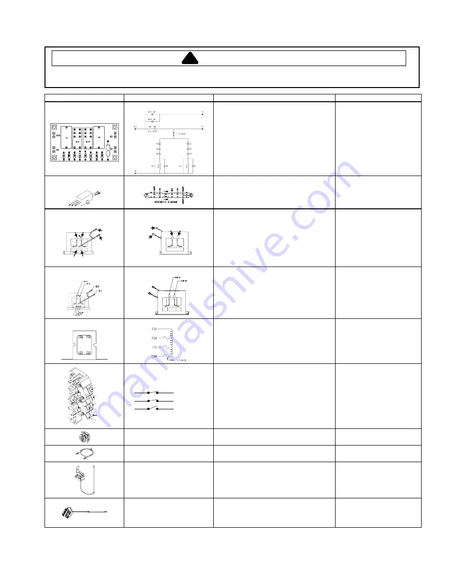
60 HZ Models only
Halfwave board
Measure voltage across terminals:
With Convection on:
E5 to MTR ...........................................
T2 to E5...............................................
E2 to E5 ..............................................
With Convection off:
E5 to MTR ...........................................
T2 to E5...............................................
E2 to E5 ..............................................
Resistance of 2 amp fuse on circuit board ..
Line voltage.
Line voltage.
Line voltage.
No voltage.
No voltage.
No voltage.
Continuity.
50 HZ Models only
Line filter
Disconnect wire from terminals.
Measure resistance from:
Blue to Blue.............................................
Brown to Brown.......................................
< 1
.
< 1
.
50 HZ Models only
COM
230 V
5
6
9
4
H. V. Transformer
8
7
9
4
Discharge Capacitor
Remove all wires from terminals.
Measure resistance from:
230 to COM.............................................
230 to Ground .........................................
Terminal 5 to 6 ........................................
Terminal 7 to 8 ........................................
Terminal 4 to Ground ..............................
Less than 1
.
Infinite.
300
.
300
.
Approx. 28.2
.
60 HZ Models only
H. V. Transformer
Discharge Capacitor
Remove all wires from terminals.
Measure resistance from:
Primary...................................................
Filament .................................................
Secondary to Ground screw on
transformer stack ...................................
Less than <1
.
Less than <1
.
Approx. 100 – 120
.
60 HZ Models only
Auto Transformer
Discharge Capacitors
Remove all wires from terminals.
Measure resistance from:
230 V to 0 V ............................................
208 V to 0 V ............................................
120 V to 0 V ............................................
Approximately 38
.
Approximately 37
.
Approximately 25
.
7
8
2
4
3
5
Interlock switch
Door Closed
2
4
7
3
5
8
Primary
Secondary
Monitor
Disconnect wires to switch.
With door open, measure resistance:
Terminal 2 to 3 ........................................
Terminal 4 to 5 ........................................
Terminal 7 to 8 ........................................
With door closed, measure resistance:
Terminal 2 to 3 ........................................
Terminal 4 to 5 ........................................
Terminal 7 to 8 ........................................
Infinite.
Infinite.
Continuity.
Continuity.
Continuity.
Infinite.
Convection blower motor
Remove wires from motor.
Measure resistance across terminals .........
Approx. 349
.
Convection heating element
(2100 W)
Disconnect wires from terminals.
Measure resistance across element ...........
Approx. 27.4
.
Thermal limiter
(Auto Reset)
(See NOTE below.)
Remove all wires from terminals.
Measure resistance across terminals .........
Thermal limiter opens when oven temp.
reaches 279° C (535° F). It automatically
resets at approx. 204° C (400° F).
Continuity.
If not, replace limiter.
Thermal limiter
(Manual Reset)
(See NOTE below.)
Remove all wires from terminals.
Measure resistance across terminals .........
Thermal limiter will open when oven
temperature reaches 279° C (535° F).........
Continuity.
If not, replace limiter.
Reset by pressing RESET.
NOTE:
Early limiters required a manual reset. This is accomplished by pressing a red reset button. Limiters
produced recently reset automatically and do not have a reset button.


