10
it will be affected by drafts, hot or cold water pipes or air
ducts in walls, radiant heat from fireplace, lamps, the sun,
television, etc. Consult the Instruction Sheet packaged with
thermostat for mounting instructions.
All units have two stages of heating and two stages of me-
chanical cooling. Units which will have economizers may
use thermostats with two or three stages of cooling. All units
can use single stage or multi-stage thermostats. Refer to
figures later in this section for wiring.
WARNING
To avoid personal injury, electrical shock or death,
disconnect electrical power before servicing or changing
any electrical wiring.
The units are designed for operation on 60 hertz current and
at voltages as shown on the rating plate. All internal wiring
in the unit is complete. It is necessary to bring in the power
supply to the contactor as shown on the unit wiring diagram
which is supplied with each unit. The low voltage wiring must
be connected between the unit control panel and the room
thermostat.
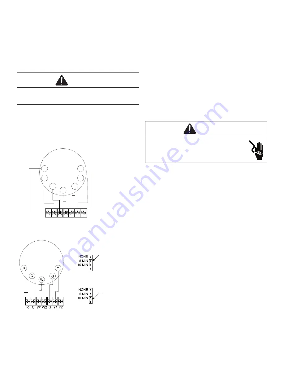
R C W1W2 G Y1 Y2
R
Y2
C
Y1
W1
G
W2
I
ntegrated
Control Module
Thermostat
Two-Stage Heating
with
Two-Stage Cooling
Two-Stage Heating with Two-Stage Cooling
Thermostat Diagram
5 MINUTE DELAY
PERIOD WITH
JUMPER IN THIS
POSITION
10 MINUTE DELAY
PERIOD WITH
JUMPER IN THIS
POSITION
Two-Stage Heating (timed) and Two-Stage Cooling (timed) with Single
Stage Thermostat Diagram
Single Stage Thermostat
To use a single stage thermostat, move jumper located to the
left of the terminal strip labeled “Stage Delay” from NONE to
“5” or “10” minutes. This selection will cause the control to
run on low stage for the selected time (5 or 10 minutes) then
shift to HIGH STAGE. This option controls both cooling and
heating modes. If the jumper is not moved, only low-stage
cool and low-stage heat will operate.
Alternate Fan Only Speed
The APG16 models are equipped with ECM variable speed
motors. Two FAN ONLY speeds are possible with these mo-
tors. To utilize the LOW HEAT blower speed for FAN ONLY
operation, connect the wire from the thermostat’s G terminal
to the ignition control board’s G terminal.
To utilize the alternate FAN ONLY speed, connect the wire
from the thermostat’s G terminal to the unstripped green
wire in the control box. (DO NOT connect the thermostat’s
G terminal to the ignition control’s G terminal.) This alternate
FAN ONLY blower speed is approximately 75% of the HIGH
COOL speed.
24 Volt Dehumidistat Wiring
WARNING
High Voltage!
Disconnect ALL power before servicing or
installing thus unit. Multiple power sources may
be present. Failure to do so may cause property
damage, personal injury, or death.
The optional usage of a dehumidistat allows the unit’s cir
-
culator blower to operate at a slightly lower speed (approx-
imately 80% of desired cooling speed) during a combined
thermostat call for cooling and dehumidistat call for dehu-
midification. This can be done through an independent de
-
humidistat. This lower blower speed enhances dehumidi-
fication of the conditioned air as it passes through the air
conditioning coil. For proper function, a dehumidistat applied
to this package unit must operate on 24 VAC and utilize a
switch which opens on humidity rise. Refer to the unit wiring
diagram for additional wiring details.
To install/connect a dehumidistat:
1. Turn OFF power to unit.
2. To enable the dehumidify function, locate the ECM
blower motor interface module in the unit’s blower
section. Locate the jumper label “HUM” on the interface
module. Cut the jumper to enable dehumidification
(see ECM Blower Motor Interface Module).
3. Secure the dehumidistat neutral wire (typically the
white lead) to the gray, unstripped wire in the unit’s
control box.
4. Secure the dehumidistat low voltage wire (typically
the black lead) to the ignition control’s “R” terminal.
5. Secure the dehumidistat ground wire (typically the
green lead) to the ground screw to the unit’s sheet
metal control box.
NOTE
: Ground wire may not be present on all
dehumidistats.
6. Turn ON power to unit.


