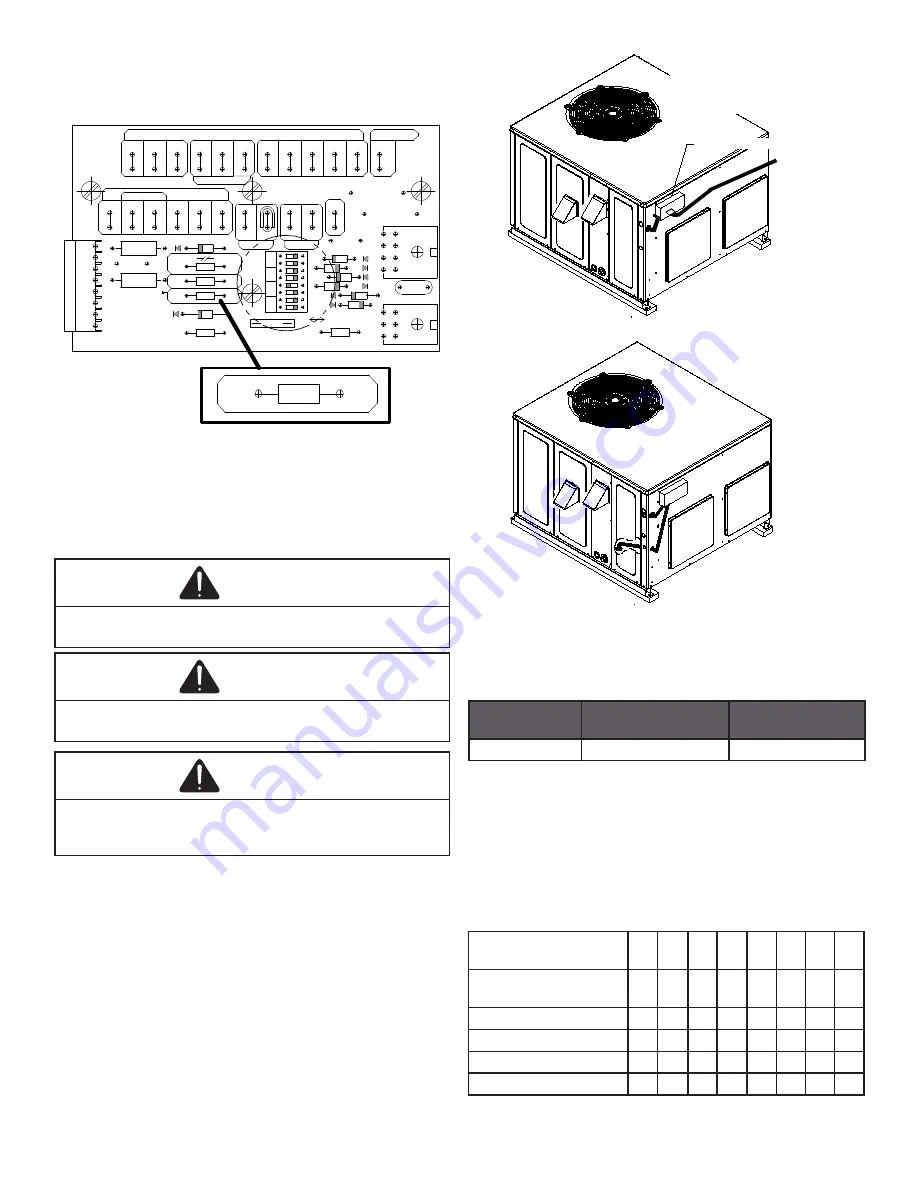
11
Once the HUM jumper is cut at the ECM motor interface
module, the dehumidify function is enabled during a com-
bination call for cooling (T-Stat) and dehumidification (DE
-
HUMStat).
5
Y1
1
SW
IT
CH
8
7
6
5
4
3
2
1
W1
OT1
OT2
HUM
PJ6
PJ2
PJ4
W2
CR9
HEATER
W1
W2
C
R
24 VAC
CR8
CR7
CR6
J3
CR5
C2
4
1
J2
CR2
DS
1
CR1
R5
O
FF
O
N
D
IP
E
F1
3A
M P
KESU
CR
1 0
R3
PN. PCB001 02
(CFM)
CONFIGURATION.
DIP SWITCH
FOR PROPER
TO MANUAL
PLEASE REFER
R1
R2
ED
W2
O
COM
YCON
R
HEATPUMP
CONDENSER
OUTDOOR
THERMOSTATS
HUMIDISTAT
HUM
Y/Y2
G
Y1
R
C
OT2
OT1
OTC
O
W/W2
E\W1
J1
HUM
PJ6
EMC Blower Motor Interface Module
Refer to the unit wiring diagram for electrical connections.
When installed, the unit must be electrically grounded in ac-
cordance with local codes or in the absence of local codes,
with the National Electrical Code, ANSI/NFPA No. 70, and/or
the CSA C22.1 Electrical Code. Ensure low voltage connec-
tions are waterproof.
WARNING
To avoid the risk of electrical ground shock, wiring to the
unit must be polarized and grounded.
CAUTION
To avoid property damage or personal injury due to fire, use
only copper conductors.
WARNING
To prevent improper and dangerous operation due to
wiring errors, label all wires prior to disconnection when
servicing controls. Verify proper operation after servicing.
For unit protection, use a fuse or
HACR
circuit breaker that
is in excess of the circuit ampacity, but less than or equal
to the maximum overcurrent protection device. DO NOT
EXCEED THE MAXIMUM OVERCURRENT DEVICE SIZE
SHOWN ON UNIT DATA PLATE.
All line voltage connections must be made through weath-
erproof fittings. All exterior power supply and ground wiring
must be in approved weatherproof conduit. Low voltage
wiring from the unit control panel to the thermostat requires
coded cable. See below for ground level and rooftop wiring.
Electrical Power Directly To Junction Box
Electrical Power Routed Through Bottom of Unit
Note:Junction box location
shown is optional and is
for illustration purposes only.
JUNCTION BOX
Electrical Power Routed Through Bottom of Unit
Typical Electrical Wiring Unit Voltage
High Voltage Wiring
Rated Voltage
Minimum Supply
Voltage
Minimum Supply
Voltage
208/230V
197
253
The unit transformer is factory connected for 230V opera-
tion. If the unit is to operate on 208V, reconnect the trans-
former primary lead as shown on the unit wiring diagram.
The induced draft blower on some models is equipped with
a low speed 230V lead (blue) and a low speed 208V lead
(black). If equipped, connect the induced draft blower low
speed 208V lead (black) in place of the low speed 230V lead
(blue). Place the unused 230V lead on the “PARK” terminal
located on ignition control.
Branch Circuit
Ampacity
15 20 25 30 35 40 45 50
SUPPLY WIRE
LENGTH - FEET
200
6
4
4
4
3
3
2
2
150
8
6
6
4
4
4
3
3
100
10
8
8
6
6
6
4
4
50
14 12 10 10
8
8
6
6


