16
4. Relight all other appliances turned off in step 1. Be
sure all pilot burners are operating.
Main Burner Flame Check
Flames should be stable, soft and blue (dust may cause or-
ange tips but they must not be yellow) and extending directly
outward from the burner without curling, floating or lifting off.
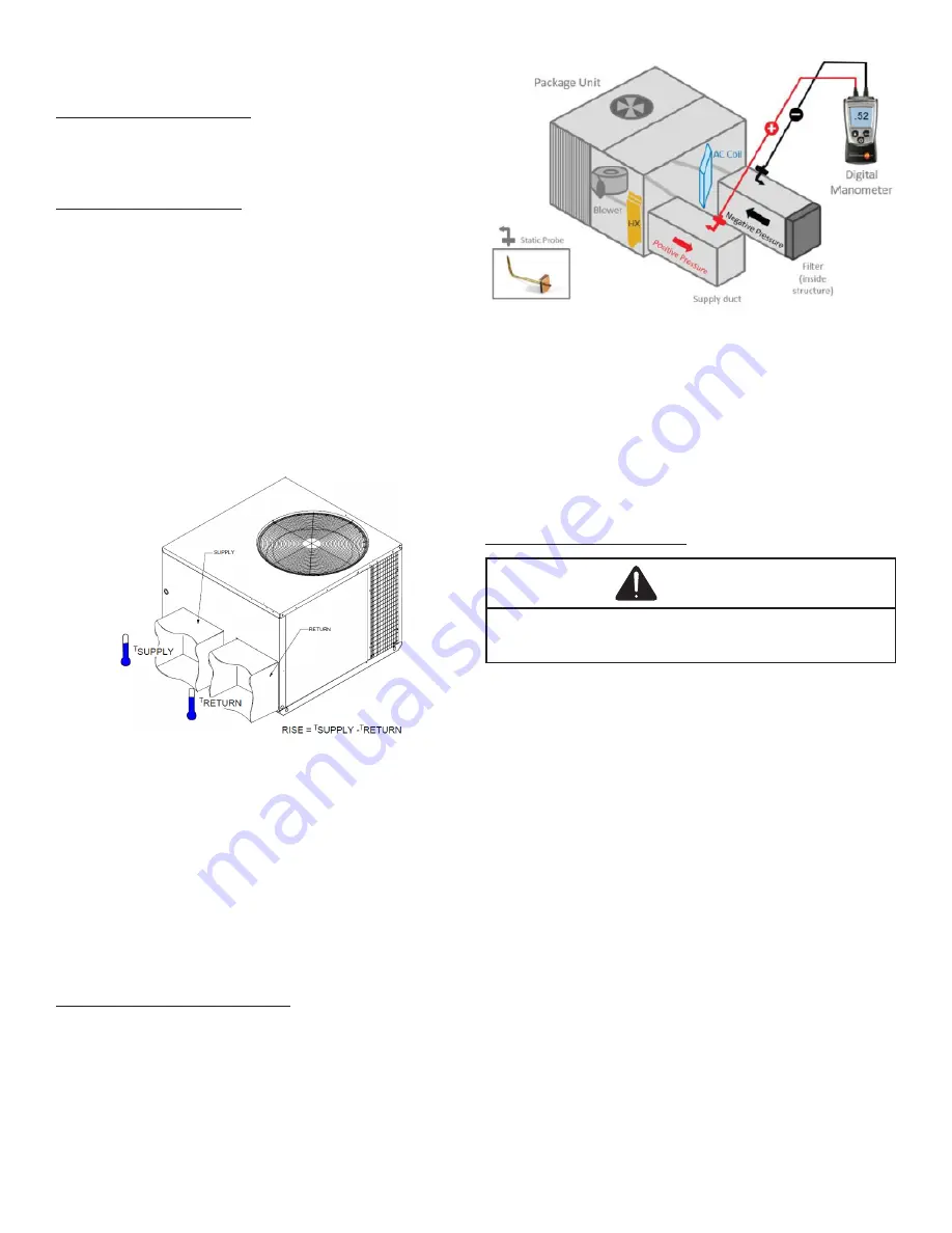
Temperature Rise Check
Check the temperature rise through the unit by placing ther-
mometers in supply and return air registers as close to the
unit as possible. Thermometers must not be able to sample
temperature directly from the unit heat exchangers, or false
readings could be obtained.
1. All registers must be open; all duct dampers must be
in their final (fully or partially open) position and the
unit operated for 15 minutes before taking readings.
2. The temperature rise must be within the range specified
on the rating plate.
NOTE:
Air temperature rise is the temperature difference be
-
tween supply and return air.
Checking Temperature Rise
With a properly designed system, the proper amount of tem-
perature rise will normally be obtained when the unit is op-
erated at rated input with the recommended blower speed.
If the correct amount of temperature rise is not obtained, it
may be necessary to change the blower speed. A higher
blower speed will lower the temperature rise. A slower blow-
er speed will increase the temperature rise.
NOTE:
Blower speed MUST be set to give the correct air
temperature rise through the unit as marked on the rating
plate.
External Static Pressure Check
The total external static pressure must be checked on this
unit to determine if the airflow is proper.
1. Using a digital manometer measure the static
pressure of the return duct at the inlet of the unit,
(Negative Pressure).
Total External Static
2. Measure the Static pressure of the supply duct,
(Positive Pressure).
3. Add the two readings together.
NOTE:
Both readings may be taken simultaneously
and read directly on the manometer if so desired.
4. Consult proper table for quantity of air.
If the external static pressure exceeds the minimum or max-
imum allowable statics, check for closed dampers, dirty fil
-
ters, undersized or poorly laid out ductwork.
Blower Speed Adjustments
WARNING
To avoid personal injury or death due to electric shock,
remove electrical power from the unit before changing
speed taps on the blower motor.
The APG16 models are equipped with ECM circulating
blower motors. ECM circulating blower motors are constant
airflow motors with very low power consumption. The ECM
motor is controlled by 24VAC signals passed from an ECM
interface module.
The ignition control board has four blower speed outputs:
LOW HEAT, HI HEAT, LOW COOL and HIGH COOL. These
are 24VAC outputs and are passed to the ECM interface
module. Depending on applied thermostat inputs, the igni-
tion control will energize the appropriate blower speed out-
put with 24VAC. This signal is passed to the ECM interface
module, which in turn passes the signal to the ECM motor.
The ECM motor then operates at the correct speed, deliver-
ing the appropriate airflow.
NOTE:
The FAN ONLY blower speed is the same as the
LOW HEAT speed unless the Alternate FAN ONLY speed is
used (see “Alternate FAN ONLY Speed” section).
The blower speed as shipped from the factory should deliver
the correct airflow. However, if installation conditions require
a different airflow, the blower speed may be adjusted using
the DIP switches on the ECM interface module (located in the
blower compartment. Use the following figure and the airflow
tables in the
Appendix
to set the desired blower speed.


