background image

8

Piping

IMPORTANT NOTE: 

To avoid possible unsatisfactory opera-

tion or equipment damage due to under firing of equipment, 

do not undersize the natural/propane gas piping from the me-

ter/tank to the unit. When sizing a trunk line, include all appli-

ances on that line that could be operated simultaneously.
The rating plate is stamped with the model number, type of 

gas and gas input rating. Make sure the unit is equipped to 

operate on the type of gas available. The gas line installa-

tion must comply with local codes, or in the absence of local 

codes, with the latest edition of the National Fuel Gas Code 

NFPA 54/ANSI Z223.1. 

Natural Gas Connection

Length of 

Pipe in Feet

1/2

3/4

1

1  1/4

1  1/2

10

132

278

520

1050

1600

20

92

190

350

730

1100

30

73

152

285

590

980

40

63

130

245

500

760

50

56

115

215

440

670

60

50

105

195

400

610

70

46

96

180

370

560

80

43

90

170

350

530

90

40

84

160

320

490

100

38

79

150

305

460

Pressure = .50 PSIG or less and Pressure Drop of 0.3" W.C. (Based 

on 0.60 Specific Gravity Gas)

Natural Gas Capacity of Pipe

in Cubic Feet of Gas Per Hour (CFH)

Nominal Black  Pipe Size (inches)

              Btuh Furnace Input

            Calorific Value of Gas

BTUH Furnace Input

Heating Value of Gas (BTU/Cubic Foot)

CFH =

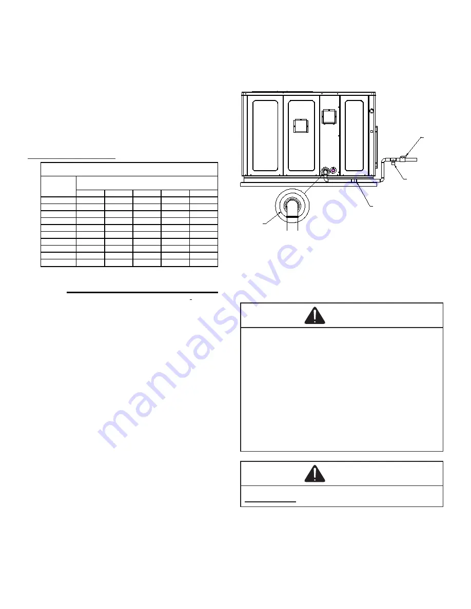
Refer to the Proper Piping Practice drawing for the general 

layout at the unit. The following rules apply: 

1.  Use black iron pipe and fittings for the supply piping.  

The  use  of  a  flex  connector  and/or  copper  piping 

is permitted as long as it is in agreement with local 

codes.

2.  Use pipe joint compound on male threads only. Pipe 

joint compound must be resistant to the action of the 

fuel used. 

3.  Use ground joint unions. 

4.  Install a drip leg to trap dirt and moisture before it can 

enter the gas valve. The drip leg must be a minimum 

of three inches long.

5.  Use two pipe wrenches when making connection to 

the gas valve to keep it from turning.

6.  Install a manual shut-off valve in a convenient location 

(within six feet of unit) between the meter and the unit.

7.  Tighten all joints securely.

8.  The unit must be connected to the building piping by 

one of the following methods:

•  Rigid metallic pipe and fittings

•  Semirigid metallic tubing and metallic fittings 

(Aluminum alloy tubing must not be used in exterior 

locations)

•  Listed gas appliance connectors used in accordance 

with the terms of their listing that are completely in 

the same room as the equipment

•  In the prior two methods above the connector or 

tubing must be protected from physical and thermal 

damage. Aluminum alloy tubing and connectors 

must be coated to protect against external corrosion 

when in contact with masonry, plaster or insulation 

or are subject to repeated wettings by liquids (water 

- not rain water, detergents or sewage)

DRIP LEG

MANUAL

SHUT-OFF

VALVE

GROUND JOINT UNION

(INSTALLED AHEAD OF GAS VALVE)

GROMMET

Proper Piping Practice

NOTE:  

The unit gas supply entrance is factory sealed with 

plugs. Keep plugs in place until gas supply is ready to be 

installed. Once ready, replace the plugs with the supplied 

grommets and install gas supply line.

Gas Piping Checks 

CAUTION

To prevent property damage or personal injury due to fire, 

the following instructions must be performed regarding gas 

connections and pressure testing.

• The units and its gas connections must be leak tested 

before placing in operation. Because of the danger of 

explosion or fire, never use a match or open flame to test 

for leaks. Never exceed specified pressures for testing. 

Higher pressure may damage gas valve and cause overfiring 

which may result in premature heat exchanger failure.

• This unit and its shut-off valve must be disconnected 

from the gas supply during any pressure testing of that 

system at pressures in excess of 1/2 PSIG (3.48 kPA).

• This unit must be isolated from the gas supply system by 

closing its manual shut-off valve during any pressure 

testing of the gas supply piping system at test pressures 

equal to or less than 1/2 PSIG (3.48 kPA).

WARNING

To avoid property damage or personal injury, be sure there is 

NO OPEN FLAME in the vicinity during air bleeding.

There will be air in the gas supply line after testing for leaks 

on a new installation. Therefore, the air must be bled from 

the line by loosening the ground joint union until pure gas is 

expelled. Tighten union and wait for five minutes until all gas 

has been dissipated in the air. Be certain there is no open 

flame in the vicinity during air bleeding procedure. The unit is 

placed in operation by closing the main electrical disconnect 

switch for the unit.

Summary of Contents for APG 16 M Series

Page 1: ...anada shown below ANSI Z21 47 CSA 2 3 Gas Fired Central Furnaces IMPORTANT This product has been designed and manufactured to meet ENERGY STAR criteria for energy efficiency when matched with appropri...

Page 2: ...bcooling 18 TROUBLESHOOTING 18 Ignition Control Error Codes 18 Fault Recall 18 Abnormal Operation Heating 18 Internal Control Failure 18 External Lockout 18 Pressure Switch Stuck Open 19 Pressure Swit...

Page 3: ...for use with this unit Serious property damage personal injury reduced unit performance and or hazardous conditions may result from the use of such non approved devices WARNING Heating unit should not...

Page 4: ...hen Tested As Outlined Above Return Doors Windows Exhaust Fans Fireplace Dampers And Any Other Gas fired Burning Appliance To Their Previous Conditions Of Use RISQUE D INTOXICATION AU MONOXYDE DE CARB...

Page 5: ...0259 216 El mon xido de carbono puede causar enfermedades severas como da o cerebral permanente muerte Las emisiones de mon xido de carbono pueden circular a trav s del aparato cuando se opera en cual...

Page 6: ...maintained The combustion air inlet and flue outlet hoods on the unit must never be obstructed If used do not allow the economizer manual fresh air damper motorized fresh air damper to become blocked...

Page 7: ...the Installation Manual provided with the LP kit for conversion from natural gas to propane gas Natural Min 5 0 W C Max 10 0 W C Propane Min 11 0 W C Max 13 0 W C INLET GAS PRESSURE Inlet Gas Pressure...

Page 8: ...metallic fittings Aluminum alloy tubing must not be used in exterior locations Listedgasapplianceconnectorsusedinaccordance with the terms of their listing that are completely in the same room as the...

Page 9: ...0 161 365 679 1 149 1 769 961 2 009 150 130 293 546 923 1 421 772 1 613 200 111 251 467 790 1 216 660 1 381 250 90 222 414 700 1 078 585 1 224 300 89 201 378 634 976 530 1 109 350 82 185 345 584 898 4...

Page 10: ...Two FAN ONLY speeds are possible with these mo tors To utilize the LOW HEAT blower speed for FAN ONLY operation connect the wire from the thermostat s G terminal to the ignition control board s G term...

Page 11: ...r HACR circuit breaker that is in excess of the circuit ampacity but less than or equal to the maximum overcurrent protection device DO NOT EXCEED THE MAXIMUM OVERCURRENT DEVICE SIZE SHOWN ON UNIT DAT...

Page 12: ...aintained The supply duct should be provided with an access panel large enough to inspect the air chamber downstream of the heat exchanger A cover should be tightly attached to prevent air leaks For d...

Page 13: ...indoor blower is de energized NOTE A 180 second anti short cycle is integral to the con trol and prevents recycling of the compressor Fan Only 1 Thermostat calls for FAN ONLY by energizing G 2 The ind...

Page 14: ...t 3 Set the room thermostat to its lowest possible setting 4 Remove the heat exchanger door on the side of the unit by removing screws 5 This unit is equipped with an ignition device which automatical...

Page 15: ...3 w c 2 0 w c High Stage 3 2 3 8 w c 3 5 w c Low Stage 5 7 6 3 w c 6 0 w c High Stage 9 7 10 3 w c 10 0 w c Gas Manifold Gas Pressure Natural Propane Manifold Gas Pressure 8 Remove regulator cover sc...

Page 16: ...uct at the inlet of the unit Negative Pressure Total External Static 2 Measure the Static pressure of the supply duct Positive Pressure 3 Add the two readings together NOTE Both readings may be taken...

Page 17: ...n the unit 7 If cooling and or air circulation will be desired turn ON the electrical power Cooling Startup NOTE The outdoor temperature must be 60 F or higher before making adjustments to charge Comp...

Page 18: ...ing to heating is desired 3 Set the room thermostat to the desired temperature TROUBLESHOOTING Ignition Control Error Codes The following presents probable causes of questionable unit operation Refer...

Page 19: ...tem peratures This can be caused by a dirty filter excessive duct static insufficient air flow or a faulty limit Check filters total external duct static blower motor blower motor speed tap see wirin...

Page 20: ...as frequently as necessary to keep the finned areas free of lint hair and debris Condenser Evaporator and Induced Draft Motors Bearings on the air circulating blower motor condenser mo tor and the com...

Page 21: ...at the thermostat Wait a few minutes since any dislodged dust will alter the normal flame appearance Flames should be predominantly blue and directed into the tubes They should not be yellow They shou...

Page 22: ...uck Closed 4 Flashes Thermal Protection Device Open 5 Flashes Flame Detected with Gas Valve Closed 6 Flashes Short Cycle Compressor Delay Cooling Only Amber Light Signal Refer to Abnormal Heating or C...

Page 23: ...120 150 180 Circulator Blower HIGH OFF Seconds Gas Valve Igniter Induced Draft Blower Thermostat 0 15 22 27 52 0 30 LOW HIGH OFF LOW OFF ON HIGH OFF LOW HIGH OFF LOW Circulator Blower Compressor Outd...

Page 24: ...PPLY ENTRANCE CONDENSATE DRAIN CONNECTION 3 4 NPT FEMALE 16 1 8 19 1 8 EVAPORATOR CONTROL PANEL ACCESS PANEL 4 3 4 B 7 15 16 16 B 5 1 2 1 3 8 16 2 3 4 A 18 7 16 FLUE EXHAUST 51 47 BLOWER ACCESS PANEL...

Page 25: ...HES CHECK FOR SHORTS IN FLAME SENSOR WIRING CHECK GAS VALVE CHECK ROLLOUT LIMIT SW CHECK AUXILIARY LIMIT SW CHECK MAIN LIMIT SWITCH CHECK WIRING FOR SHORTS CHECK PRESSURE SWITCH PRESSURE SWITCH CLOSED...

Page 26: ...on 4 Ton Min Filter Size 1 20 x 25 x1 1 25 x 25 x 1 1 25 x 25 x 1 2 20 x 20 x 1 2 20 x 20 x 1 Clearance in accordance with local installation codes the requirements of the gas supplier and the manufac...

Page 27: ...X Not recommended for heating application NOTE The shaded area indicates ranges in excess of maximum external static pressure allowable when heating For satisfactory operation external static pressure...

Page 28: ...28 CFM OUTPUT AND DIP SWITCH SETTINGS...

Page 29: ...motor is hermetically sealed and does not require additional oiling Annual Inspection Qualified Servicer Only Your package unit should be inspected by a qualified install er or service agency at leas...

Page 30: ...Type NG Natural Gas LP Liquid Propane Residential Package Outdoor Section ELECTRICAL Supply Voltage Measure L1 and L2 Voltage L1 L2 Compressor Amps Condenser Fan Amps PRESSURES TEMPERATURES Suction Ci...

Page 31: ...31 THIS PAGE IS LEFT INTENTIONALLY BLANK...

Page 32: ...in all product comments Please fill out the feedback form on one of the following links Amana Brand Products http www amana hac com about us contact us You can also scan the QR code on the right for...

Reviews: