background image

9

PROPANE GAS INSTALLATIONS

IMPORTANT NOTE:

 For Natural gas to LP gas conversion, 

Conversion Kit “LPM-08” must be used. Consult your dealer 

for appropriate conversion kit(s).
All propane gas equipment must conform to the safety stan-

dards of the National Board of Fire Underwriters (See NBFU 

Manual 58).
For satisfactory operation, propane gas supply pressure 

must be within 9.7 - 10.3 inches W.C. at the manifold with all 

gas appliances in operation. Maintaining  proper gas pres-

sure depends on three main factors:

1.  Vaporization rate, which depends on (a) temperature 

of the liquid, and (b) wetted surface area of the 

container or containers.

2.  Proper pressure regulation. 

3. Pressure drop in lines between regulators, and 

between second stage regulator and the appliance. 

Pipe size required will depend on length of pipe run 

and total load of all appliances.

Tanks and Piping

Complete information regarding tank sizing for vaporization, 

recommended regulator settings and pipe sizing is available 

from most regulator manufacturers and propane gas suppliers.
Since propane gas will quickly dissolve white lead or most 

standard com mercial compounds, special pipe dope must 

be used. Shellac base compounds resistant to the actions 

of liquefied petroleum gases such as Gasolac

®

, Stalactic

®

Clyde’s

®

 or John Crane

®

 are satisfactory.

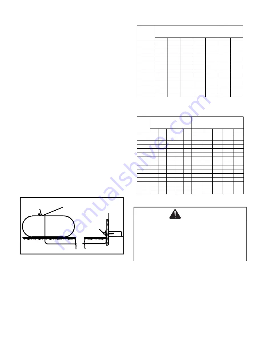
See Typical  Propane  Gas  Piping  figure  for  typical  piping 

arrangement.

200 PSIG

Maximum

5 to 15 PSIG

(20 PSIG Max.)

Continuous

11" W.C.

Second Stage

Regulator

First Stage

Regulator

Typical Propane Gas Piping

Sizing Between First and Second Stage Regulator

Maximum Propane Capacities listed are based on 1 PSIG Pressure Drop at 10

PSIG Setting.  Capacities in 1,000 BTU/HR

3/8"

1/2"

5/8"

3/4"

7/8"

1/2"

3/4"

30

309

700

1,303

2,205

3,394

1,843

3,854

40

265

599

1,115

1,887

2,904

1,577

3,298

50

235

531

988

1,672

2,574

1,398

2,923

60

213

481

896

1,515

2,332

1,267

2,649

70

196

446

824

1,394

2,146

1,165

2,437

80

182

412

767

1,297

1,996

1,084

2,267

90

171

386

719

1,217

1,873

1,017

2,127

100

161

365

679

1,149

1,769

961

2,009

150

130

293

546

923

1,421

772

1,613

200

111

251

467

790

1,216

660

1,381

250

90

222

414

700

1,078

585

1,224

300

89

201

378

634

976

530

1,109

350

82

185

345

584

898

488

1,020

400

76

172

321

543

836

454

949

To convert to Capacities at 15 PSIG Settings -- Multiply by 1.130

To convert to Capacities at 5 PSIG Settings -- Multiply by 0.879

PIPE OR

TUBING

LENGTH,

FEET

NOMINAL PIPE SIZE,

SCHEDULE 40

TUBING SIZE, O.D., TYPE L

Sizing Between Single or Second Stage Regulator and Appliance*

Maximum Propane Capacities Listed are Based on 1/2" W.C. Pressure Drop at

11" W.C. Setting.  Capacities in 1,000 BTU/HR

3/8"

1/2"

5/8"

3/4"

7/8"

1/2"

3/4"

1"

1-1/4"

1-1/2"

10

49

110

206

348

539

291

608

1,146

2,353

3,525

20

34

76

141

239

368

200

418

788

1,617

2,423

30

27

61

114

192

296

161

336

632

1,299

1,946

40

23

52

97

164

253

137

284

541

1,111

1,665

50

20

46

86

146

224

122

255

480

985

1,476

60

19

42

78

132

203

110

231

436

892

1,337

80

16

36

67

113

174

94

198

372

764

1,144

100

14

32

59

100

154

84

175

330

677

1,014

125

12

28

52

89

137

74

155

292

600

899

150

11

26

48

80

124

67

141

265

544

815

200

10

22

41

69

106

58

120

227

465

697

250

9

19

36

61

94

51

107

201

412

618

300

8

18

33

55

85

46

97

182

374

560

350

7

16

30

51

78

43

89

167

344

515

400

7

15

28

47

73

40

83

156

320

479

*DATA IN ACCORDANCE WITH NFPA PAMPHLET NO. 54

NOMINAL PIPE SIZE,

SCHEDULE 40

TUBING SIZE, O.D., TYPE L

PIPE OR

TUBING

LENGTH,

FEET

Propane Gas Pipe Sizing

WARNING

To avoid property damage or serious personal injury due to 

fire or explosion caused by a propane gas leak, install a gas 

detecting warning device. If the propane gas unit is installed 

in an excavated area or a confined space, a warning device is 

required due to:

• Propane gas is heavier than air and any leaking gas can 

settle in any low areas or confined spaces.

• Propane gas odorant may fade, making the gas 

undetectable except with a warning device.

ELECTRICAL WIRING

Thermostat Location

Mount  the  thermostat  approximately  five  feet  above  the 

floor, in an area that has an inside, vibration-free wall  and 

has good air circulation.
Movement of air must not be obstructed by furniture, door, 

draperies, etc. The thermostat must not be mounted where 

Summary of Contents for APG 16 M Series

Page 1: ...anada shown below ANSI Z21 47 CSA 2 3 Gas Fired Central Furnaces IMPORTANT This product has been designed and manufactured to meet ENERGY STAR criteria for energy efficiency when matched with appropri...

Page 2: ...bcooling 18 TROUBLESHOOTING 18 Ignition Control Error Codes 18 Fault Recall 18 Abnormal Operation Heating 18 Internal Control Failure 18 External Lockout 18 Pressure Switch Stuck Open 19 Pressure Swit...

Page 3: ...for use with this unit Serious property damage personal injury reduced unit performance and or hazardous conditions may result from the use of such non approved devices WARNING Heating unit should not...

Page 4: ...hen Tested As Outlined Above Return Doors Windows Exhaust Fans Fireplace Dampers And Any Other Gas fired Burning Appliance To Their Previous Conditions Of Use RISQUE D INTOXICATION AU MONOXYDE DE CARB...

Page 5: ...0259 216 El mon xido de carbono puede causar enfermedades severas como da o cerebral permanente muerte Las emisiones de mon xido de carbono pueden circular a trav s del aparato cuando se opera en cual...

Page 6: ...maintained The combustion air inlet and flue outlet hoods on the unit must never be obstructed If used do not allow the economizer manual fresh air damper motorized fresh air damper to become blocked...

Page 7: ...the Installation Manual provided with the LP kit for conversion from natural gas to propane gas Natural Min 5 0 W C Max 10 0 W C Propane Min 11 0 W C Max 13 0 W C INLET GAS PRESSURE Inlet Gas Pressure...

Page 8: ...metallic fittings Aluminum alloy tubing must not be used in exterior locations Listedgasapplianceconnectorsusedinaccordance with the terms of their listing that are completely in the same room as the...

Page 9: ...0 161 365 679 1 149 1 769 961 2 009 150 130 293 546 923 1 421 772 1 613 200 111 251 467 790 1 216 660 1 381 250 90 222 414 700 1 078 585 1 224 300 89 201 378 634 976 530 1 109 350 82 185 345 584 898 4...

Page 10: ...Two FAN ONLY speeds are possible with these mo tors To utilize the LOW HEAT blower speed for FAN ONLY operation connect the wire from the thermostat s G terminal to the ignition control board s G term...

Page 11: ...r HACR circuit breaker that is in excess of the circuit ampacity but less than or equal to the maximum overcurrent protection device DO NOT EXCEED THE MAXIMUM OVERCURRENT DEVICE SIZE SHOWN ON UNIT DAT...

Page 12: ...aintained The supply duct should be provided with an access panel large enough to inspect the air chamber downstream of the heat exchanger A cover should be tightly attached to prevent air leaks For d...

Page 13: ...indoor blower is de energized NOTE A 180 second anti short cycle is integral to the con trol and prevents recycling of the compressor Fan Only 1 Thermostat calls for FAN ONLY by energizing G 2 The ind...

Page 14: ...t 3 Set the room thermostat to its lowest possible setting 4 Remove the heat exchanger door on the side of the unit by removing screws 5 This unit is equipped with an ignition device which automatical...

Page 15: ...3 w c 2 0 w c High Stage 3 2 3 8 w c 3 5 w c Low Stage 5 7 6 3 w c 6 0 w c High Stage 9 7 10 3 w c 10 0 w c Gas Manifold Gas Pressure Natural Propane Manifold Gas Pressure 8 Remove regulator cover sc...

Page 16: ...uct at the inlet of the unit Negative Pressure Total External Static 2 Measure the Static pressure of the supply duct Positive Pressure 3 Add the two readings together NOTE Both readings may be taken...

Page 17: ...n the unit 7 If cooling and or air circulation will be desired turn ON the electrical power Cooling Startup NOTE The outdoor temperature must be 60 F or higher before making adjustments to charge Comp...

Page 18: ...ing to heating is desired 3 Set the room thermostat to the desired temperature TROUBLESHOOTING Ignition Control Error Codes The following presents probable causes of questionable unit operation Refer...

Page 19: ...tem peratures This can be caused by a dirty filter excessive duct static insufficient air flow or a faulty limit Check filters total external duct static blower motor blower motor speed tap see wirin...

Page 20: ...as frequently as necessary to keep the finned areas free of lint hair and debris Condenser Evaporator and Induced Draft Motors Bearings on the air circulating blower motor condenser mo tor and the com...

Page 21: ...at the thermostat Wait a few minutes since any dislodged dust will alter the normal flame appearance Flames should be predominantly blue and directed into the tubes They should not be yellow They shou...

Page 22: ...uck Closed 4 Flashes Thermal Protection Device Open 5 Flashes Flame Detected with Gas Valve Closed 6 Flashes Short Cycle Compressor Delay Cooling Only Amber Light Signal Refer to Abnormal Heating or C...

Page 23: ...120 150 180 Circulator Blower HIGH OFF Seconds Gas Valve Igniter Induced Draft Blower Thermostat 0 15 22 27 52 0 30 LOW HIGH OFF LOW OFF ON HIGH OFF LOW HIGH OFF LOW Circulator Blower Compressor Outd...

Page 24: ...PPLY ENTRANCE CONDENSATE DRAIN CONNECTION 3 4 NPT FEMALE 16 1 8 19 1 8 EVAPORATOR CONTROL PANEL ACCESS PANEL 4 3 4 B 7 15 16 16 B 5 1 2 1 3 8 16 2 3 4 A 18 7 16 FLUE EXHAUST 51 47 BLOWER ACCESS PANEL...

Page 25: ...HES CHECK FOR SHORTS IN FLAME SENSOR WIRING CHECK GAS VALVE CHECK ROLLOUT LIMIT SW CHECK AUXILIARY LIMIT SW CHECK MAIN LIMIT SWITCH CHECK WIRING FOR SHORTS CHECK PRESSURE SWITCH PRESSURE SWITCH CLOSED...

Page 26: ...on 4 Ton Min Filter Size 1 20 x 25 x1 1 25 x 25 x 1 1 25 x 25 x 1 2 20 x 20 x 1 2 20 x 20 x 1 Clearance in accordance with local installation codes the requirements of the gas supplier and the manufac...

Page 27: ...X Not recommended for heating application NOTE The shaded area indicates ranges in excess of maximum external static pressure allowable when heating For satisfactory operation external static pressure...

Page 28: ...28 CFM OUTPUT AND DIP SWITCH SETTINGS...

Page 29: ...motor is hermetically sealed and does not require additional oiling Annual Inspection Qualified Servicer Only Your package unit should be inspected by a qualified install er or service agency at leas...

Page 30: ...Type NG Natural Gas LP Liquid Propane Residential Package Outdoor Section ELECTRICAL Supply Voltage Measure L1 and L2 Voltage L1 L2 Compressor Amps Condenser Fan Amps PRESSURES TEMPERATURES Suction Ci...

Page 31: ...31 THIS PAGE IS LEFT INTENTIONALLY BLANK...

Page 32: ...in all product comments Please fill out the feedback form on one of the following links Amana Brand Products http www amana hac com about us contact us You can also scan the QR code on the right for...

Reviews: