17
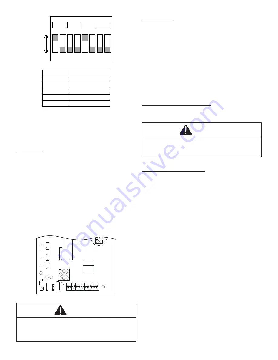
DIP
SWITCH
1 2 3 4 5 6 7 8
ON
• • • • • • • •
OFF
• • • • • • • •
Factory Dipswitch Settings
Switches
Function
1, 2
Heating Speeds
3
Unused
4
OFF for Two-Stage
5, 6
Cooling Speeds
7, 8
Airflow Adjust
DIP Switch Functions
NOTE:
Heating airflow must be adjusted to provide the tem
-
perature rise shown on rating plate. Blower speeds are pro-
grammed to deliver adequate airflow at rated external static
pressure (ESP). Refer to airflow table provided in the
Ap
-
pendix
for details.
Limit Check
Check limit control operation after 15 minutes of operation
by blocking the return air grille(s).
1. After several minutes the main burners must go
OFF. Blower will continue to run.
2. Remove air restrictions and main burners will relight
after a cool down period of a few minutes.
Adjust the thermostat setting below room temperature.
1. Main burners must go OFF.
2. Circulating Air Blower will continue to run for 90,
120, 150 or 180 seconds, depending on the setting.
NOTE:
If necessary, adjust fan OFF delay settings to obtain
satisfactory comfort level.
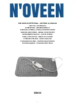
LO COOL
HI COOL
LO HEAT
HI HEAT
U6
U7
U4
U5
U3
K2
K1
P1
ECON
STAGE
DELAY
SPEEDUP
SW1
FAULT
RECALL
BLOWER
OFF DELAY
F1
R C W1 W2 G Y1 Y2
Control Board (Top)
WARNING
This unit must not be used as a “construction heater” during
the finishing phases of construction on a new structure. This
type of use may result in premature failure of the unit due
to extremely low return air temperatures and exposure to
corrosive or very dirty atmosphere.
Unit Shutdown
1. Set the thermostat to lowest setting.
2. Turn off the electrical power supply to the unit.
3. Remove the heat exchanger door on the side of the
unit by removing screws.
4. Move the gas control valve switch to the OFF position.
Do not force.
5. Close manual gas shutoff valve external to the unit.
6. Replace the heat exchanger door on the unit.
7. If cooling and/or air circulation will be desired, turn
ON the electrical power.
Cooling Startup
NOTE:
The outdoor temperature must be 60°F or higher
before making adjustments to charge.
Compressor Protection Devices
The compressor includes components which are designed to
protect the compressor against abnormal operating conditions.
WARNING
To prevent personal injury or death, always disconnect
electrical power before inspecting or servicing the
unit. NOTE: All compressor protection devices reset
automatically, energizing the contactor and outdoor fan.
Cooling Refrigerant Charging
Check unit charge before putting the cooling section into full
operation. The unit has a thermostatic expansion valve me-
tering device. To ensure the unit is properly charged for the
intended application, check the unit refrigerant sub-cooling at
the condenser. The refrigerant sub-cooling is a function of out-
door ambient temperature and return air temperature of the
conditioned space. It is the installing contractors responsibility
to ensure the proper refrigerant sub-cooling at the condenser
is adjusted for each application. As the outdoor ambient tem-
perature rises the sub-cooling decreases and as the outdoor
ambient temperature lowers, the sub-cooling increases.
NOTE:
Proper sub-cooling adjustment optimizes cooling
performance. Models equipped with thermostatic expansion
valve, charge the system to sub-cooling, range shown on
chart, when necessary, adjust expansion valve stem for su-
perheat setting.
SUPERHEAT
Checking Superheat
Refrigerant gas is considered superheated whenever its
temperature is higher than the saturation temperature cor-
responding to its pressure. The degree of superheat equals
the degrees of temperature increase above the saturation
temperature at existing pressure.
1. Run system at least 10 minutes to allow pressure to
stabilize.
2. Temporarily install thermometer on suction (large) line
near compressor with adequate contact and insulate
for best possible reading.


