background image

Troubleshooting

October 2000

RT1300056 Rev.1

5

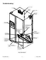
Door gaskets

Gaskets foamed in place between door
liner and door pan during manufacture.

If gasket is damaged, replace with appropriate service gasket kit. Consult
your parts manual for kit part numbers. Follow instructions in kit.

Refrigerator and
freezer doors

Foamed as assemblies during
manufacture.

Door liner and door pan are not replaceable. If either is damaged, door must
be replaced. Consult your service manual for door replacement instructions.

Water tube

Water tube for dispenser runs through
conduit in freezer door.

To replace water tube:
1. 

Remove toe grille.

2. 

Remove plastic union nut at tube splice below freezer door.

3. 

Attach nylon cord or fishing line to upper end of water tube.

4. 

Pull tube out of door from bottom. Be sure to leave about a foot of cord
dangling at both ends of conduit.

Attach new water tube to lower end of cord. Grasp upper end of cord and pull
tube though conduit, into place.

To remove water filter bracket and filter head assembly:
1. 

Loosen two screws securing water filter bracket to fresh food liner.

2. 

Slide bracket with filter head forward approximately ½". Bracket drops
down when screw heads reach keyhole slots.

3. 

Unscrew filter head from bracket.

Detach water tubes from filter head by pushing in on collars while pulling out
on tubes.

Water head assembly
and filter

Unit ships with bypass plug in water head
assembly and filter canister in crisper.

Bypass plug should be retained in case
filter becomes plugged and new cartridge
is not readily available.

To remove bypass or filter from head assembly, turn bypass or filter a
quarter-turn counterclockwise and pull down. It is not necessary to shut off
water supply before changing filter.

!

WARNING

To avoid risk of electrical shock that can cause death or severe personal injury, disconnect unit from power before
servicing unless tests require power. Discharge capacitors through a 10,000-ohm resistor before handling. Wires
removed during disassembly must be replaced on correct terminals to ensure proper grounding and polarization.

Summary of Contents for ARS9167A

Page 1: ...ce Controls in Normal Position Kw 24 hr 0 4 Percent Run Time 10 Cycles 24 hr 25 Refrigerator Compartment Average Food Temperature 3 F Freezer Compartment Average Food Temperature 3 F Ambient F 65 90 110 65 90 110 65 90 110 65 90 110 65 90 110 ARS9167A ARS9168A ARS9169A 1 2 2 5 4 0 31 63 100 26 19 0 35 35 35 1 5 0 1 Temperature Relationship Test Chart T 1 Outlet 3 F T 1 Inlet 3 F T 3 Suction Line 7...

Page 2: ... load Resistance Run Windings Start Windings Fan Cooled R134a refrigerant 850 BTUH 115 VAC 60 Hz 149 watts 21 3 amps 1 5 amps 2 60 ohms 4 35 ohms R9900109 Control damper Settings 1 4 7 Closing temperatures 47 F 40 F 30 F R0161092 Control freezer temperature Settings 1 in 1 out 4 in 4 out 7 in 7 out Temperatures 21 0 F 4 5 F 13 3 F 5 9 F 9 8 F 11 0 F WARNING To avoid risk of electrical shock that c...

Page 3: ...nits with serial No prefix 0006 through June 2000 Diameter of fan blade on these units is 5 25 Volt Rotation facing end opposite shaft RPM Watt 115 VAC 60 Hz Clockwise 2500 RPM 12 15 watts 10449505 Motor evaporator fan Used on all units with serial No prefix 0007 starting July 2000 Diameter of fan blade on these units is 3 85 Volts Rotation facing end opposite shaft Speed Watts 115 VAC 60 Hz Clock...

Page 4: ... until either 48 6 F or 15 8 F is reached 10530703 Timer defrost Volt Defrost period minutes Defrost cycle hours 120 VAC 60 Hz 33 3 6 8 12313403 Valve water primary Volt Watt Purple coil Brown coil Water pressure inlet Max Min Fill rate 120 VAC 60 Hz 20 watts 20 watts 120 PSI 20 PSI 137 14 24 CC s at 7 5 seconds 12313404 Valve water secondary Volt Watt Purple coil Brown coil Water pressure inlet M...

Page 5: ...ough conduit into place To remove water filter bracket and filter head assembly 1 Loosen two screws securing water filter bracket to fresh food liner 2 Slide bracket with filter head forward approximately Bracket drops down when screw heads reach keyhole slots 3 Unscrew filter head from bracket Detach water tubes from filter head by pushing in on collars while pulling out on tubes Water head assem...

Page 6: ...AKER COIL BROWN WATER TANK SECONDARY SOLENOID VALVE ICEMAKER COIL BROWN SECONDARY SOLENOID VALVE WATER DISPENSER COIL PURPLE 1 4 O D X 5 16 O D PLASTIC COMPRESSION UNION SECONDARY SOLENOID VALVE INLET PRIMARY SOLENOID VALVE WATER DISPENSER COIL PURPLE ICE WATER DISPENSER WATER FILTER INLET HOUSEHOLD WATER LINE CONNECTION 1 4 O D COPPER TUBE COMPRESSION FITTING ...

Page 7: ... by pushing AUTO LIGHT button located on control façade Green light above AUTO LIGHT button indicates sensor is active Dispenser Lock Prevents operation of water and ice dispensers To activate or deactivate lock press and hold DISPENSER LOCK button for 3 seconds Green light above button indicates dispenser lock Automatic Lock Out Shuts down both ice and water mechanisms of dispenser when either me...

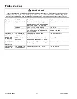
Page 8: ...r See Instruction 2 on Page 10 for wiring diagram Replace door if both heaters have failed No LED s lit PCB Power supply If no LED s turn on and wiring checks OK PCB is defective Replace PCB Failed water actuator switch Remove both leads from switch and measure resistance across switch terminals Press finger against actuator to close switch Resistance should read less than 1Ω in this position and ...

Page 9: ...ec Otherwise PCB needs replaced Replace PCB Bulb burnt out Measure resistance across bulb filament If higher than 1k Ω replace bulb Replace bulb Harness Open white wire between cavity light and splice in door Wire not connected at light socket Inspect wire for proper connection at 10 pin connector and cavity light socket Ohmmeter should show short between white wire at cavity light and neutral on ...

Page 10: ...lens Clean lens area of control Night light on all the time Cavity light works properly comes on when ice or water actuated PCB Defective photo sensor circuit If night light is on all the time and procedure above has been preformed PCB is defective Replace PCB Cavity light all the time Ice and water work OK Incorrect harness wiring Verify wire colors on 10 pin connector against the wiring diagram ...

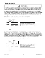
Page 11: ...wire In cavity cut white wire two inches from 10 pin connector Splice violet wire and one Blk Wh wire to two inch stub of white wire at 10 pin connector Tape off loose end of white wire Next cut brown wire two inches from Pin 3 on 10 pin connector Splice second Blk Wh wire to two inch stub of Brown wire at 10 pin connector Tape off loose end of brown wire NOTE Never wire in both heaters at the sam...

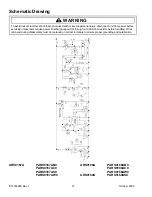
Page 12: ...169A PARS9169AS0 WARNING To avoid risk of electrical shock that can cause death or severe personal injury disconnect unit from power before servicing unless tests require power Discharge capacitors through a 10 000 ohm resistor before handling Wires removed during disassembly must be replaced on correct terminals to ensure proper grounding and polarization ...

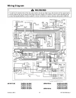
Page 13: ...9A PARS9169AS0 WARNING To avoid risk of electrical shock that can cause death or severe personal injury disconnect unit from power before servicing unless tests require power Discharge capacitors through a 10 000 ohm resistor before handling Wires removed during disassembly must be replaced on correct terminals to ensure proper grounding and polarization ...

Reviews: