background image

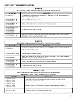
PRODUCT IDENTIFICATION

14

Model/Rev

Description

CAUF*****6AA

Initial release of CAUF Dayton Upflow/Downflow coils.

CAUF*****6BA

Burr Oak Louvered Fin released in place of the Wavy Fin.

CAUF****6*DA

Replaced existing copper coils and other associated parts with aluminum components.

CAUF*****6DB

Drain pan material changed.

CAUF1824A6RDB

CAUF1824B6RDB

CAUF36***CA

Redesign from 2 row to 3 row for performance improvement. 

CAUF3030(A/B)6RDB

CAUF3030(C/D)6RDB
CAUF3131(B/C)6RDB

CAUFA*****6A*

Initial Release.

CAUFA*****6B*

CAUFA*****6C*

Manufacturing Location Change from Dayton to Houston. Designated by "R".

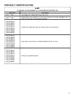
CAUF

C-INDOOR COIL A-UPFLOW/DOWNFLOW UNCASED FLOWRATOR

Manufacturing Location Change from Dayton to Houston. Designated by "R".

Major revision update for A-Chassis drain port relocation

Summary of Contents for ASXC16

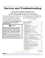
Page 1: ...ment servicing or repair of the equipment specified in this manual or attempting to install adjust service or repair the equipment specified in this manual without proper training may result in product damage property damage personal injury or death WARNING 2020 2021 Goodman Manufacturing Company L P Brand is a registered trademark of Maytag Corporation or its related companies and is used under l...

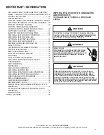
Page 2: ...ine for dealers Your telephone company will bill you for the call UNLOADER TEST PROCEDURE WITH COMFORT ALERT UNITARY UC CONTROL DIAGNOSTICS 40 LOCKED ROTOR TEST 40 OPERATION TEST 41 TESTING CRANKCASE HEATER OPTIONAL ITEM 41 CHECKING REVERSING VALVE AND SOLENOID 42 TESTING DEFROST CONTROL 42 TESTING TEMPERATURE SENSORS COMMUNICATING READY MODELS ONLY 42 AVPTC MBVC HEATER CONTROL 43 ELECTRIC HEATER ...

Page 3: ...of refrigerants WARNING The compressor POE oil for R 410A units is extremely susceptible to moisture absorption and could cause compressor failure Do not leave system open to atmosphere any longer than necessary for installation WARNING To avoid possible explosion Never apply flame or steam to a refrigerant cylinder If you must heat a cylinder for faster charging partially immerse it in warm water...

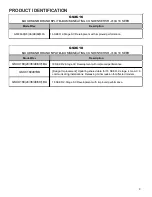
Page 4: ...PRODUCT IDENTIFICATION 4 ...

Page 5: ...PRODUCT IDENTIFICATION 5 ...

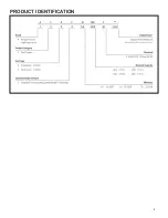
Page 6: ...4 5 6 7 8 9 10 11 Design Series Electrical MB Modular Blower 1 208 230 60 1 Revisions Motor Speed A First Series V Variable Speed ECM Motor C Circuit Breaker A No Circuit Breaker B Circuit Breaker 12 1200 CFM 16 1600 CFM 20 2000 CFM 01 ComfortBridgeTM ...

Page 7: ...roved performance ASXC16 AMANA BRAND SPLIT X COMMUNICATING CONDENSERS R 410A 16 SEER Model Rev Description ASXC18 1AA Initial release of Amana brand 2 stage 16 SEER condensing units with R 410A communicating models ASXC180 36 48 60 1AB Wiring diagram updated with notes ASXC180 36 48 60 1AC Replaced compressors ZPS20K4EPFV230 with ZPS20K5EPFV130 and compressor ZPS30K4EPFV230 with ZPS30K5EPFV130 ASX...

Page 8: ...Rev Description GSXC180 24 36 48 60 1BA 18 SEER 2 Stage AC Development with improved performance GSXC180481BB Design Improvement Updating shared data for 18 SEER 2 stage 4 ton AC in communicating installations Releasing minor revision for affected models GSXC180 24 36 48 60 1BA 18 SEER 2 Stage AC Development with improved performance GSXC18 GOODMAN BRAND SPLIT X COMMUNICATING CONDENSERS R 410A 18 ...

Page 9: ...or changed to Nidec DSXC160241AF DSXC160481BE Refrigerant charge reduction DSXC16 DELUXE SPLIT X COMMUNICATING CONDENSERS R 410A 16 SEER Model Rev Description DSXC18 1AA Initial release of Goodman Deluxe brand 2 stage 18 SEER condensing units with R 410A communicating models DSXC180 36 48 60 1AB Wiring diagram updated with notes DSXC18036AC Replaced compressors ZPS20K4EPFV230 with ZPS20K5EPFV130 a...

Page 10: ...24 36 1CA ASZC160 48 60 1CA Replaced compressors with Copeland s UltraTech 3 lineup Transitioned coils to 7mm Offers improved performance ASZC16 AMANA BRAND SPLIT Z COMMUNICATING HEAT PUMP R 410A 16 SEER Model Rev Description ASZC180 1AA Introduces Amana brand 2 stage 18 SEER heat pump units with R 410A communicating models ASZC180601BC ASZC180601BB Ultratech 2 0 compressor change ASZC180 36 48 60...

Page 11: ...tioned coils to 7mm Offers improved performance GSZC16 GOODMAN BRAND SPLIT Z COMMUNICATING HEAT PUMP R 410A 16 SEER Model Rev Description GSZC180 24 36 48 60 Replaced compressors with Copeland s UltraTech 3 lineup Transitioned coils to 7mm Offers improved performance GSZC18 GOODMAN BRAND SPLIT Z COMMUNICATING HEAT PUMP R 410A 16 SEER ...

Page 12: ... pump units with R 410A communicating models DSZC180 36 48 60 1AB Sanhua RANCO reversing valves DSZC180361AD Replaced compressors ZPS20K4EPFV230 with ZPS20K5EPFV130 and compressor ZPS30K4EPFV230 with ZPS30K5EPFV130 DSZC180 36 48 1AC DSZC180601BA Release of models with accumulators and crankcase heaters DSZC160 24 48 1AD DSZC160601BB Ultratech 2 0 compressor change DSZC18 DELUXE SPLIT Z COMMUNICATI...

Page 13: ...AVPTC49D14BA AVPTC59C14BA AVPTC59D14BA AVPTC61D14BA ECM Based Air Handler with New Comfort Bridge Compatible PCB Control Board MBVC 01 SINGLE PIECE AIR HANDLER MULTIPLE POSITION VARIABLE SPEED PAINTED TXV WITH 4 WIRE COMMUNICATING CONTROL Model Rev Description MBVC1201 MBVC1601 MBVC2001 ECM Based Air Handler with New Comfort Bridge Compatible PCB Control Board NOTE This service manual contains AVP...

Page 14: ... 6DB Drain pan material changed CAUF1824A6RDB CAUF1824B6RDB CAUF36 CA Redesign from 2 row to 3 row for performance improvement CAUF3030 A B 6RDB CAUF3030 C D 6RDB CAUF3131 B C 6RDB CAUFA 6A Initial Release CAUFA 6B CAUFA 6C Manufacturing Location Change from Dayton to Houston Designated by R CAUF C INDOOR COIL A UPFLOW DOWNFLOW UNCASED FLOWRATOR Manufacturing Location Change from Dayton to Houston...

Page 15: ...PF3642C6CA CHPF3642D6CA CHPF3743C6BA CHPF3743D6BA CHPF4860D6DA Louvered fins Replaced copper tube hairpins with aluminum hairpins CHPF1824A6CB CHPF2430B6CB CHPF3636B6CB CHPF3642C6CB CHPF3642D6CB CHPF3743C6BB CHPF3743D6BB CHPF4860D6DB Drain pan material change to a Decabromodiphenyl Ether free resin CHPF1824A6CC CHPF2430B6CC CHPF3636B6CC CHPF3642C6CC CHPF3642D6CC CHPF3743C6BC CHPF3743D6BC CHPF4860D...

Page 16: ...C CAPF3030B6DC CAPF3030C6DC CAPF3030D6DC CAPF3131B6DC CAPF3131C6DC CAPF3137B6AB CAPF3636A6DC CAPF3636B6DC CAPF3636C6DC CAPF3636D6DC CAPF3642C6DC CAPF3642D6DC CAPF3743C6DC CAPF3743D6DC CAPF4860C6DC CAPF4860D6DC CAPF4961C6DC CAPF4961D6DC CAPFA1818B6A CAPFA1818B6A CAPFA 6A Initial Release CAPFA 6B CAPFA 6C Redesign the wrapper for the CAPF to provide increased ease of installation CAPF C INDOOR COIL ...

Page 17: ...B CAPT3743D4AB CAPT4961C4AB CAPT4961D4AB Redesign the wrapper for the CAPT to provide increased ease of installation CAPT C INDOOR COIL A UPFLOW DOWNFLOW PAINTED CASED FLOWRATOR W TXV Model Rev Description CSCF 6AA Initial release of 13 SEER CSCF horizontal slab coils CSCF 6BA Burr Oak Louvered Fin released in place of the Wavy Fin Rows reduced by one where applicable CSCF1824N6BB CSCF3036N6BB CSC...

Page 18: ...n sends the demand to the ECM motor The following table lists the various communicating systems the operating mode and airflow demand source For example assume the system is an air conditioner matched with an air handler With a call for low stage cooling the air conditioner will calculate the system s low stage cooling airflow demand The air conditioner will then send a fan request along with the ...

Page 19: ...on LED Indicates network traffic The table below indicates the LED status and the corresponding potential problem Learn Button Used to reset the network Depress the button for approximately 2 seconds to reset the network Communications Troubleshooting Chart LED LED Status Indication Possible Causes Corrective Action s Notes Cautions Green Receive LED Off No Power Communications error No power to a...

Page 20: ...w pressure saturated refrigerant enters the tubes of the indoor coil a portion of the liquid immediately vaporizes It continues to soak up heat and vaporizes as it proceeds through the coil cooling the indoor coil down to about 48 F Heat is continually being transferred to the cool fins and tubes of the indoor evaporator coil by the warm system air This warming process causes the refrigerant to bo...

Page 21: ...ensor The OCT sensor is clamped to a feeder tube entering the outdoor coil Defrost timing periods of 30 60 90 or 120 minutes may be selected via the dipswitch settings on the UC PCB During operation if the coil temperature is low enough approximately 31 F the microprocessor will accumulate the compressor run time When the total compressor run time reaches 30 60 90 or 120 minutes and there is a cal...

Page 22: ...rol voltage 2 If voltage is present loosen the nut on the top of the coil Remove the coil there should be slight resistance 3 If the slight resistance is felt remove the coil As you remove the coil listen carefully an audible click should be detected The clicking is due to the movement of the pilot valve plunger The absence of a clicking sound indicates the plunger is stuck Troubleshooting Mechani...

Page 23: ... delays have expired NOTE The only time auxiliary emergency heat can be utilized is when the system is connected legacy and a heat pump thermostat is utilized 2 0 Heating Operation Auxiliary Emergency Heat 2 1 The thermostat sends a request for emergency heat to the air handler 2 2 The air handler control energizes the ECM blower motor at the emergency heat speed The electric heat sequencer output...

Page 24: ...nd switches the condenser fan motor to high speed 1 8 The system operates at high stage heat pump heating 1 9 If the thermostat demand cannot be met on high stage heat pump heating 1 10 Upon receiving a demand for auxiliary heat the air handler control determines the appropriate airflow for high stage heat pump auxiliary heat operation and operates the ECM blower motor at that airflow demand The a...

Page 25: ... The compressor will energize or re energize at high stage 3 3 The UC control sends a request for defrost operation to the integrated air handler control The air handler control energizes the electric heat sequencer outputs and operates the ECM blower model at the electric heat speed 3 4 Once the defrost cycle is terminated the heat pump commands the air handler modular blower to end defrost opera...

Page 26: ...ltage Voltage Min Max 208 230 198 253 NOTE When operating electric heaters on voltages other than 240 volts refer to the System Operation section on electric heaters to calculate temperature rise and air flow Low voltage may cause insufficient heating Checking Wiring WARNING High Voltage Disconnect all power before servicing or installing Multiple power sources may be present Failure to do so may ...

Page 27: ...requires a single W input from the thermostat Internal algorithms will control all available cooling and heating stages based on these inputs Any single stage 24VAC thermostat can be used For proper operation the thermostat must be setup to control a single stage AC outdoor unit and to control single stage electric heat operation The control board does not accommodate an O wire thermostat input re...

Page 28: ... two stage electric heat kit control the system only needs a single W input Internal algorithms will control staging automatically based on the single W input For non communicating outdoor unit wiring see instructions below 1 Use the wiring diagrams on the next page to connect low voltage thermostat wires NOTE When installing the air handler with a non communicating heat pump wire directly to the ...

Page 29: ...o HI using the push buttons or Cool Cloud HVAC phone application If the humidistat opens on humidity or the thermostat de energizes this terminal when dehumidification is required set the Dehum Logic Menu to Lo using the push buttons or Cool Cloud HVAC phone application Auxiliary Alarm Switch The control is equipped with a 24VAC Aux Alarm to be used for a condensate switch install designated by CO...

Page 30: ...te fan only airflow for the accessory using the indoor unit push button menus or the Cool Cloud HVAC phone application 5 Using the thermostat independently test each accessory in addition to the independently testing continuous fan mode ...

Page 31: ...t Use Y W G signals Thermostat has a Dehum or Configurable terminal with Dehum option Yes No Does your thermostat have a whole house Dehumidifier setting Install Dehumidistat in living space or return duct If the Dehumidistat opens on a rise on humidity then you will set Dehum logic to Low via Coolcloud app or push buttons If the Dehumidistat closes on a rise in humidity then you will set Dehum lo...

Page 32: ... voltage side of transformer R to C 3 No voltage indicates faulty transformer bad wiring or bad splices 4 Check transformer primary voltage at incoming line voltage connections and or splices 5 If line voltage available at primary voltage side of transformer and wiring and splices good transformer is inoperative Replace Checking Time Delay Relay Time delays are used in electric heaters to sequence...

Page 33: ... and voltage Checking Fan Relay Contacts ECM Fan Motor 1 Disconnect fan motor harness from plug on the UC board 2 Energize the system in low stage and check voltage Pin 5 Blue wire to Pin 3 Yellow wire 24VAC 3 Energize the system in high stage and check voltage Pin 5 Blue wire to Pin 3 Yellow wire 24VAC Pin 5 Blue wire to Pin 1 White wire 24 VAC 4 If voltage is present at these pins plug harness i...

Page 34: ...ble short 5 Apply power to unit and set thermostat to cool and set for all for cool 6 High pressure switch should open at 610 PSIG 10 PSIG and close at 420 PSIG 25 PSIG 7 If high pressure switch does not operate in these parameters replace switch Test 2 Testing High Pressure Control in Heating Mode 1 Connect refrigerant gages to unit 2 Disconnect power to indoor unit 3 Remove control panel cover 4...

Page 35: ...uit The capacitor also reduces the line current to the motor by improving the power factor The line side of this capacitor is marked with COM and is wired to the line side of the circuit Resistance Check Using A Digital Multi Meter WARNING High Voltage Disconnect all power before servicing or installing Multiple power sources may be present Failure to do so may cause property damage personal injur...

Page 36: ...he ComfortBridge Air Handlers models utilize an Emerson 4 wire variable speed ECM blower motor The ECM blower motor provides constant CFM The motor is a serially communicating variable speed motor Only four wires are required to control the motor Vdc Common Receive and Transmit The Vdc and Common wires provide power to the motor s low voltage control circuits General Checks Considerations 1 Check ...

Page 37: ...OFF Not Rotating Replace motor control end bell verify motor see Motor Checks below 9 Depress the orange power button to turn off motor 10 Disconnect power Disconnect diagnostic tool 11 Reconnect the 4 wire harness from control board to motor Electrical Checks High Voltage Power Circuits WARNING High Voltage Disconnect all power before servicing or installing Multiple power sources may be present ...

Page 38: ...low Replace the control end bell if any of the capacitors are bulging or swollen 7 Locate the 3 circuit connector in the control end bell Using an ohmmeter check the resistance between each terminal in the connector If the resistance is 100 W or greater the control end bell is functioning properly Replace the control end bell if the resistance is lower than 100 W 8 Reassemble motor and control end...

Page 39: ...em is essential at the time of manufacture and during servicing To reduce the possibility of external ignition all open flame electrical power and other heat sources should be extinguished or turned off prior to servicing a system If the following test indicates shorted grounded or open windings see procedures for the next steps to be taken Resistance Test Each compressor is equipped with an inter...

Page 40: ...der on and off at ten second intervals by applying and removing Y2 voltage to the module Wait five seconds after power is applied to Y2 before taking a reading An increase in compressor amperage should be observed when switching from part load to full load and a reduction in compressor amperage should be observed when changing from full load to part load The percent change in current depends on th...

Page 41: ...t were disconnected at the nearest point to the compressor and connect the common start and run clips to the respective leads 3 Connect good capacitors of the right MFD and voltage rating into the circuit as shown 4 With power ON close the switch WARNING Line voltage now present A If the compressor starts and continues to run the cause for failure is somewhere else in the system B If the compresso...

Page 42: ...lace it Testing Defrost Control Legacy Models Communicating Units To check the defrost control for proper sequencing proceed as follows With power ON unit not running 1 Set thermostat to call for heating 2 Press TEST and RECALL buttons simultaneously for approximately 3 seconds then release them System should go into defrost immediately 3 Using VOM check for voltage across terminals C O Meter shou...

Page 43: ...and diagnostic features Basic Operation The air handler control receives thermostat inputs from a 24VAC thermostat For cooling and heat pump operation the control operates the variable speed blower motor at the demand as determined from the thermostat input s If a demand for electric heat is received the control will provide a 24VAC output for up to two electric heat sequencers Troubleshooting Mot...

Page 44: ...intermittent operation Typical 18 AWG thermostat wire may be used to wire the system components One hundred feet is the maximum length of wire between indoor and outdoor units or between indoor unit and thermostat When outdoor transformer is used and there at least three thermostat wires running to the outdoor unit use one of the extra wires to connect the two 24 volt commons together This will en...

Page 45: ... information below for setting options Comfort Setting Menu CFS There are 6 options available in the Comfort Setting Menu which impacts system target run time and electric heat functionality Electric heat operation adjustments only apply if a communicating heat pump is installed Comfort Setting Options 1 5 have set values for the System Target Runtime and option 6 enables additional menus to custo...

Page 46: ...in if it fails to do so the strike count against the furnace will be reset and the furnace will remain the temporary primary heat source until the Under Target Threshold is reached again The system will automatically make adjustments in an attempt to satisfy the thermostat as close to this target runtime as possible After a power cycle or mode change cooling to heating or heating to cooling the sy...

Page 47: ...ing or installing Multiple power sources may be present Failure to do so may cause property damage personal injury or death 1 Remove the wiring from the control terminals 2 Using an ohmmeter test for continuity across the normally closed contacts No reading indicates the control is open replace if necessary IF FOUND OPEN REPLACE DO NOT WIRE AROUND Checking Heater Fuse Link Optional Electric Heater...

Page 48: ...and soapy water to identify leaks If you prefer to use an electronic leak detector charge the system to 10 PSIG with the appropriate system refrigerant see Serial Data Plate for refrigerant identification Do not use an alternative refrigerant Using dry nitrogen finish charging the system to 450 PSIG Apply the leak detector to all suspect areas When leaks are discovered repair the leaks and repeat ...

Page 49: ...ging WARNING REFRIGERANT UNDER PRESSURE Do not overcharge system with refrigerant Do not operate unit in a vacuum or at negative pressure Failure to follow proper procedures may cause property damage personal injury or death CAUTION Use refrigerant certified to AHRI standards Used refrigerant may cause compressor damage and is not covered under the warranty Most portable machines cannot clean used...

Page 50: ...RS6200006 NOTE Superheat adjustments should not be made until indoor ambient conditions have stabilized This could take up to 24 hours depending on indoor temperature and humidity Before checking superheat run the unit in cooling for 10 15 minutes or until refrigerant pressures stabilize Use the following guidelines and methods to check unit operation and ensure that the refrigerant charge is with...

Page 51: ...erence is 11 Superheat The 11 Superheat would fall in the range of allowable superheat 4 Disconnect manifold set installation is complete SUBCOOLING FORMULA SATURATED LIQUID TEMP LIQUID LINE TEMP NOTE Check the Schrader ports for leaks and tighten valve cores if necessary Install caps finger tight HEAT PUMP HEATING CYCLE The proper method of charging a heat pump in the heat mode is by weight with ...

Page 52: ...ading in Temperature Pressure Chart and reading to the left find the temperature in the F Column 6 The difference between the thermometer reading and pressure to temperature conversion is the amount of subcooling Add charge to raise subcooling Recover charge to lower subcooling Subcooling Formula Sat Liquid Temp Liquid Line Temp EXAMPLE A Liquid Line Pressure 417 B Corresponding Temp F 120 C Therm...

Page 53: ...iring afield installed access fitting TAILPIECE 3 8 SWEAT 7 8 NUT DISTRIBUTOR BODY PISTON SEAL EVAPORATOR COIL 1 4 FLARE CONNECTION BULB SUCTION LINE EXPANSION VALVE REMOVE BEFORE INSTALLING EXPANSION VALVE SEAL SUPPLIED W KIT SEAL SUPPLIED W KIT BULB TO BE LOCATED AT 10 OR 2 O CLOCK TAILPIECE 3 8 SWEAT 7 8 NUT DISTRIBUTOR BODY PISTON SEAL For Applications not requiring afield installed access fit...

Page 54: ... 60 8 6 162 0 57 0 264 0 87 4 366 0 110 4 468 0 129 0 600 0 149 0 62 10 0 164 0 57 7 266 0 87 9 368 0 110 8 470 0 129 3 604 0 149 5 64 11 3 166 0 58 4 268 0 88 4 370 0 111 2 472 0 129 7 608 0 150 1 66 12 6 168 0 59 0 270 0 88 9 372 0 111 6 474 0 130 0 612 0 150 6 68 13 8 170 0 59 8 272 0 89 4 374 0 112 0 476 0 130 3 616 0 151 2 70 15 1 172 0 60 5 274 0 89 9 376 0 112 4 478 0 130 7 620 0 151 7 72 1...

Page 55: ...9 88 86 84 82 80 78 308 90 88 86 84 82 80 317 92 90 88 86 84 82 326 94 92 90 88 86 84 335 96 94 92 90 88 86 345 98 96 94 92 90 88 354 100 98 96 94 92 90 364 102 100 98 96 94 92 374 104 102 100 98 96 94 384 106 104 102 100 98 96 395 108 106 104 102 100 98 406 110 108 106 104 102 100 416 112 110 108 106 104 102 427 114 112 110 108 106 104 439 116 114 112 110 108 106 450 118 116 114 112 110 108 462 1...

Page 56: ... at least 15 minutes Compare the pressure to the temperature of the coldest coil since this is where most of the refrigerant will be If the pressure indicates a higher temperature than that of the coil temperature non condensables are present Non condensables are removed from the system by first removing the refrigerant charge replacing and or installing liquid line drier evacuating and recharging...

Page 57: ...f a refrigeration system is very important in relation to system capacity proper oil return to compressor pumping rate of compressor and cooling performance of the evaporator POE oils maintain a consistent viscosity over a large temperature range which aids in the oil return to the compressor however there will be some installations which require oil return traps These installations should be avoi...

Page 58: ...einstall top cover and position blade 4 Reconnect electrical power and check for proper operation Cleaning Outdoor Fan Blade 1 Check balance weights on fan blade 2 Check fan blade setscrew for tightness Electrical Controls and Wiring 1 Disconnect power to both outdoor and indoor units 2 Check all electrical connections for tightness 3 Tighten all screws on electrical connections 4 Connections that...

Page 59: ...nt Loose or disconnected wiring connection at circulator motor power leads Open circuit in inductor or loose wiring connection at inductor 3 4 Hp and 1 Hp models only Failed circulator blower motor Tighten or correct wiring connection Verify continuous circuit through inductor Replace if open or short circuit Check circulator blower motor No Air Handler operation Eb1 Integrated control module has ...

Page 60: ...tor if necessary No Air Handler operation Eb6 Circulator blower motor shuts down for over or under voltage condition Circulator blower motor shuts down due to over temperature condition on power module High or low AC line voltage to air handler High ambient temperatures Check power to air handler Verify line voltage is within the range specified on the rating plate No Air Handler operation Eb7 Cir...

Page 61: ...for two stage heat pumps t on Indoor Airflow for non communicating outdoor units values based on 400CFM per ton default 3 0 Ton Ct F Cooling Airflow Trim default 0 CAP Cooling Airflow Profile setting default profile D shown as 4 Cnd Cooling Airflow On Delay Time default 5 seconds CFd Cooling Airflow Off Delay Time default 60 seconds CSt Percentage of high stage cooling airflow to run during low st...

Page 62: ...run during the next heat call if the heat pump fails to satisfy the custom target time for this number of consecutive cycles default 20 cycles vt t Menu is enabled if the CFS menu is set to 6 if the addition of low stage electric heat is able to consecutively satisfy the thermostat under the set target time for this number of cycles the system will transition to the heat pump for primary heating S...

Page 63: ... comm units HP1 Compressor Heat Low Stage comm Units HP2 Compressor Heat High Stage comm Units Ht Electric Heat Single Stage Ht1 Electric Heat Single Stage Ht2 Electric Heat High Stage dft Defrost Single Stage Electric Heat non comm units df1 Defrost Low Stage Electric Heat df2 Defrost High Stage Electric Heat dHU Dehumidification If a system is a heat pump connected legacy then a DFT will show on...

Page 64: ... Menu Navigation and Selection Instructions Using Phone Application over Bluetooth Network 1 Connect to the air handler instructions provided by phone during connection process 2 Select desired settings menu 3 Select item that requires adjustment and make necessary selection 4 Submit Changes Using On Board Push Buttons 1 Use the Right and Left Buttons to scroll between menus 2 Use the Center Butto...

Page 65: ...D s display the indicated code ON 1 Flash OFF ON if call present OFF if no call Low Pressure CO Trip Low refrigerant charge Restriction in liquid line Indoor blower motor failure Indoor thermostat set extremely low Verify refrigerant charge adjust as needed Check for restricted liquid line repair replace as needed Check indoor blower motor repair replace as needed Check low pressure switch repair ...

Page 66: ...s needed Check outdoor fan motor wir ing repair replace as needed Check outdoor fan motor capac itor replace as needed Turn power OFF prior to repair Replace with correct replacement part s Compressor and outdoor fan are off Low pressure switch trip 3 times within same thermostat demand Thermostat demand is present Integrated control module diagnostic status LED s display the indicated code ON 2 F...

Page 67: ...ompressor wiring repair replace as needed Turn power OFF prior to repair Fault will clear after 1 normal cycle Fault may be cleared by cycling 24VAC to control Replace with correct replacement part s Compressor and outdoor fan are off Low pressure and high pressure switches are closed Integrated control module diagnostic sta tus LED s display the indicated code OFF 6 Flashes OFF ON if call present...

Page 68: ...to control Faulty compressor wiring Check compressor repair replace as needed Check wiring repair replace as needed Turn power OFF prior to repair Must clear fault by cycling 24VAC to control Replace with correct replacement part s Air conditioner heat pump may appear to be operating normally Compressor protector may be open compressor and outdoor fan off Integrated control module diagnostic statu...

Page 69: ...f needed Turn power OFF prior to repair Fault will clear if secondary volt age rises above 21VAC Replace with correct replacement part s Compressor is off Integrated control module diagnostic sta tus LED s display the indicated code OFF ON ON ON if call present OFF if no call Comp Protector Open No current through run or start windings Compressor run winding is open Compressor not properly wired t...

Page 70: ...SERVICING 70 PCBHR104 PCBHR105 ...

Page 71: ...le diagnostic status LED display shows the indicated code BLANK E E Board misoperation Compressor relay contacts welded Replace control Turn power OFF prior to repair Replace with correct replacement part Air conditioner heat pump fails to operate Integrated control module diagnostic status LED display shows the indicated code BLANK b 0 Circulator blower motor is not running when it should be runn...

Page 72: ...or the integrated control module Verify system type communicating or legacy Populate correct shared data using Bluetooth Shared Data Loader BTSDL01 Wire system as legacy system Turn power OFF prior to repair Use Bluetooth Shared Data Loader BTSDL01 for your specific model Insert Bluetooth Shared Data Loader BTSDL01 BEFORE turning power ON Bluetooth Shared Data Loader BTSDL01 may be removed after d...

Page 73: ...er BTSDL01 BEFORE turning power ON Bluetooth Shared Data Loader BTSDL01 may be removed after data is loaded Turn power OFF before removing Bluetooth Shared Data Loader BTSDL01 Error code will be cleared once data is loaded Very long run time Four consecutive compressor protector trips with average run time between trips greater than 3 hours Compressor operating at high spped and outdoor fan operat...

Page 74: ... Check and clean the condenser coil Check outdoor fan motor repair replace as needed Check outdoor fan motor wiring repair replace as needed Check outdoor fan motor capacitor replace as needed Turn power OFF prior to repair Fault will clear after 4 consecutive normal cycles Fault may be cleared by cycling 24VAC to control Replace with correct replacement part s Compressor and outdoor fan are off T...

Page 75: ...ed Check wiring repair replace as needed Verify line voltage is within range on rating plate control local utility is out of range Turn power OFF prior to repair Must clear fault by cycling 24VAC to control Replace with correct replacement part s Compressor and outdoor fan are off for greater than 4 hours Low pressure and high pressure switches are closed Integrated control module diagnostic statu...

Page 76: ...or wiring Check compressor repair replace as needed Check wiring repair replace as needed Turn power OFF prior to repair Fault will clear after 1 normal cycel Fault may be cycling 24VAC to control Replace with correct replacement part s Compressor and outdoor fan are off Low pressure and high pressure switches are closed Open run circuit has been detected 4 times with 5 minute delay between each d...

Page 77: ...Check transformer replace if needed Turn power OFF prior to repair Fault will clear if secondary voltage rises above 21 VAC Replace with correct replacement part s Compressor is off Integrated control module diagnostic status LED display shows the indicated code BLANK P 0 Comp Protector Open No current through run or start windings Compressor run winding is open Compressor not properly wired to co...

Page 78: ...c status LED display shows the indicated code BLANK E E Board Misoperation Compressor relay contacts welded Replace control Turn power OFF prior to repair Replace with correct replacement part Air conditioner heat pump fails to operate Integrated control module diagnostic status LED display shows the indicated code BLANK b 0 Circulator blower motor is not running when it should be running Indoor b...

Page 79: ...m type communicating or legacy Populate correct shared data using Bluetooth Shared Data Loader BTSDL01 Wire system as legacy system Turn power OFF prior to repair Use Bluetooth Shared Data Loader BTSDL01 for your specific model Insert Bluetooth Shared Data Loader BTSDL01 BEFORE turning power ON Bluetooth Shared Data Loader BTSDL01 may be removed after data is loaded Turn power OFF before removing ...

Page 80: ...d Data Loader BTSDL01 BEFORE turning power ON Bluetooth Shared Data Loader BTSDL01 may be removed after data is loaded Turn power OFF before removing Bluetooth Shared Data Loader BTSDL01 Error code will be cleared once data is loaded Very long run time Four consecutive compressor protector trips with average run time between trips greater than 3 hours Compressor operating at high spped and outdoor...

Page 81: ... Check and clean the condenser coil Check outdoor fan motor repair replace as needed Check outdoor fan motor wiring repair replace as needed Check outdoor fan motor capacitor replace as needed Turn power OFF prior to repair Fault will clear after 4 consecutive normal cycles Fault may be cleared by cycling 24VAC to control Replace with correct replacement part s Compressor and outdoor fan are off T...

Page 82: ...ed Check wiring repair replace as needed Verify line voltage is within range on rating plate control local utility is out of range Turn power OFF prior to repair Must clear fault by cycling 24VAC to control Replace with correct replacement part s Compressor and outdoor fan are off for greater than 4 hours Low pressure and high pressure switches are closed Integrated control module diagnostic statu...

Page 83: ...or wiring Check compressor repair replace as needed Check wiring repair replace as needed Turn power OFF prior to repair Fault will clear after 1 normal cycel Fault may be cycling 24VAC to control Replace with correct replacement part s Compressor and outdoor fan are off Low pressure and high pressure switches are closed Open run circuit has been detected 4 times with 5 minute delay between each d...

Page 84: ...Check transformer replace if needed Turn power OFF prior to repair Fault will clear if secondary voltage rises above 21 VAC Replace with correct replacement part s Compressor is off Integrated control module diagnostic status LED display shows the indicated code BLANK P 0 Comp Protector Open No current through run or start windings Compressor run winding is open Compressor not properly wired to co...

Page 85: ...WIRING DIAGRAMS Wiring is subject to change Always refer to the wiring diagram on the unit for the most up to date wiring 85 3 Phase Heat Kit 25kW Heat Kit ...

Page 86: ...REA LOW VOLTAGE AREA E29 E24 CS NOTE 1 SEE NOTE 6 SEE NOTE 6 SEE NOTE 6 NOTE SEE INSTALLATION MANUAL FOR R C WIRING OF AIR CONDITIONER CONTROL BLACK BLUE BLUE PINK STRIPE BROWN ORANGE PURPLE RED WHITE YELLOW YELLOW PINK STRIPE CONTACTOR CRANKCASE HEATER CRANKCASE HEATER SWITCH CONDENSER FAN MOTOR COMPRESSOR COMPRESSOR SOLENOID DISCHARGE THERMOSTAT HIGH PRESSURE SWITCH INTERNAL OVERLOAD LOW PRESSUR...

Page 87: ...UTDOOR UNIT R GR YL BK RD LPS HPS RVS HP ONLY COMPONENT CODE C CONTACTOR CH CRANKCASE HEATER CHS CRANKCASE HEATER SWITCH CM CONDENSER FAN MOTOR COMP COMPRESSOR CS COMPRESSOR SOLENOID DT DISCHARGE THERMOSTAT HPS HIGH PRESSURE SWITCH IO INTERNAL OVERLOAD LPS LOW PRESSURE SWITCH OAS OUTDOOR AIR SENSOR OCS OUTDOOR COIL TEMP SENSOR RCCF RUN CAPACITOR FOR COMPRESSOR FAN RVS REVERSING VALVE SOLENOID SC S...

Page 88: ...THE IO MANUAL LOCATED IN COMMUNICATING THERMOSTAT KIT FOR MORE DETAILS FROM OUTDOOR UNIT GND L1 L2 BK YL YL CM RES 2 5 1 SR SC OPTIONAL HARD START L1 L2 K2 C R S COMP R S 1 2 5 CCH SC C UC CONTROL HERM CAP COM SR OPTIONAL HARD START K6 ECM FAN MOTOR C CHS BK BK RD RD RD YL BK RD 0140R00192 E RD BL WH PU YL OR FROM OUTDOOR UNIT R GR YL BK 1 2 R C E25 RD LPS HPS RVS COMPONENT CODE C CONTACTOR CH CRA...

Page 89: ...AND C TERMINALS ARE NOT TO BE USED FOR 2 STAGE COMMUNICATING HEAT PUMP APPLICATIONS FOR COMMUNICATING HEAT PUMPS OR IF ONLY TWO THERMOSTAT WIRES ARE AVAILABLE A SEPARATE TRANSFORMER MUST BE INSTALLED IN THE OUTDOOR UNIT FOR CONTROL BOARD POWER 1 AND 2 WIRES ARE REQUIRED FOR ALL APPLICATIONS SEE INSTALLATION MANUAL FOR FULL SYSTEM WIRING EXAMPLES COLOR CODES BL BLUE RD RED YL YELLOW OR ORANGE BK BL...

Page 90: ...C TERMINALS ARE NOT TO BE USED FOR 2 STAGE COMMUNICATING HEAT PUMP APPLICATIONS FOR COMMUNICATING HEAT PUMPS OR IF ONLY TWO THERMOSTAT WIRES ARE AVAILABLE A SEPARATE TRANSFORMER MUST BE INSTALLED IN THE OUTDOOR UNIT FOR CONTROL BOARD POWER 1 AND 2 WIRES ARE REQUIRED FOR ALL APPLICATIONS SEE INSTALLATION MANUAL FOR FULL SYSTEM WIRING EXAMPLES COLOR CODES BL BLUE RD RED YL YELLOW OR ORANGE BK BLACK ...

Page 91: ...ATING OF AT LEAST 105 C USE COPPER CONDUCTORS ONLY 4 UNIT MUST BE PERMANENTLY GROUNDED AND CONFORM TO N E C AND LOCAL CODES 5 TO RECALL THE LAST 6 FAULTS DEPRESS THE RIGHT PUSH BUTTON FROM STATUS MENU ONCE AND THEN USE THE LEFT OR RIGHT BUTTON TO REVIEW ALL THE FAULTS HISTORY 6 2 GREEN LEDS INDICATES CLIMATE TALK AND DATAAC NETWORK TRAFFIC STATUS USE LEARN MENU FOR CLIMATE TALK NETWORK RESET 7 DIS...

Page 92: ...contact us Amana Brand Products http www amana hac com about us contact us You can also scan the QR code on the right for the product brand you purchased to be directed to the feedback page GOODMAN BRAND AMANA BRAND 2020 2021 Goodman Manufacturing Company L P Brand is a registered trademark of Maytag Corporation or its related companies and is used under license All rights reserved ...

Reviews: