RS1500000 Rev. 2
18
Component Testing
To avoid risk electrical shock, personal injury, or death,
always disconnect electrical power source to the freezer
before attempting to service, unless test procedures require
power to be connected. When removing any wiring from terminals they must be replaced on the same terminals.
Ensure all ground wires are connected before certifying unit as repaired and/or operational.
WARNING
!
PTC Relay
PTC relay is a push-on type that mounts to the start and
run terminals of the compressor. It is a magnetic switch
with starting contacts. Its magnetic coil is in series with
the run winding of the compressor.
When current is applied to the compressor, the magnetic
coil raises the relay plunger and closes the starting
contacts, connecting the start winding in parallel with the
run winding. As the compressor motor approaches
running speed, current in the run winding and in the relay
coil decreases and plunger drops out opening the start
winding circuit. Compressor motor continues to operate
on the run winding.
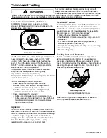
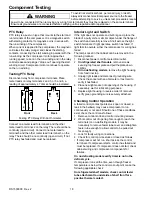
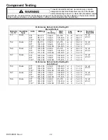
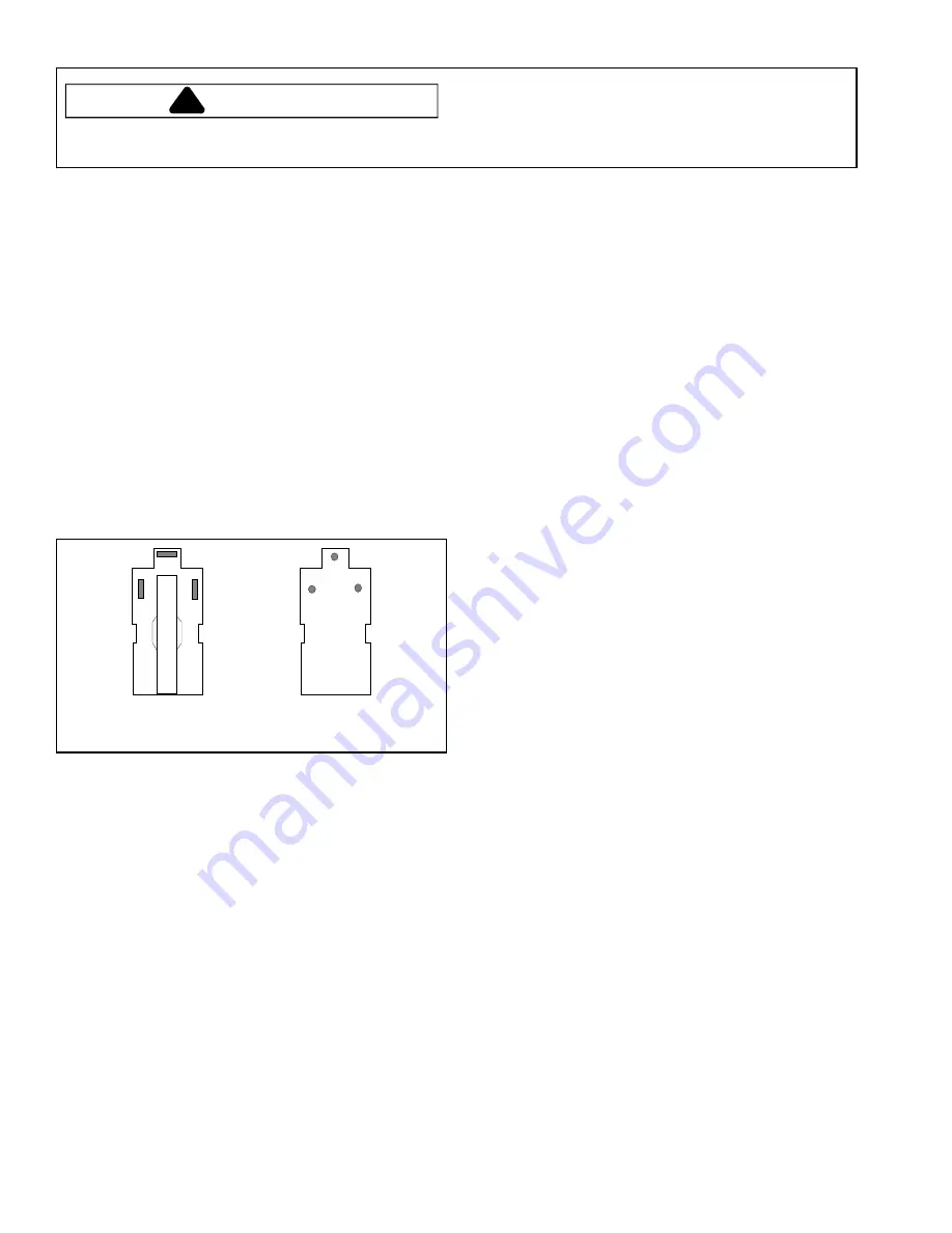
Testing PTC Relay
Disconnect relay from compressor terminals. Place
meter leads on relay terminals 2 and 3, or 5 and 6, a
reading of approximately 4.7 ohms should be indicated.
1
2
3
4
8
6
5
7
Front
Back
Testing PTC Relay With An Ohmmeter
Connect one meter lead to terminal 8 and the other
meter lead to terminal 2 on the relay. There should be no
continuity (open circuit). Connect one meter lead to
terminal 8 and the other meter lead to terminal 3 on the
relay. There should be no continuity (open circuit). If not,
PTC relay has failed and must be replaced.
Interior Light and Switch
If the light does not operate and bulb is good, place the
blade of a putty knife or similar object under the flange of
the switch and carefully remove. Short across the light
switch terminals. If light operates, switch has failed. If
light fails to operate, either the lamp socket or wiring has
failed.
The lamp socket in the cabinet can be removed in the
following manner:
1. Disconnect power cord from electrical outlet.
2.
On refrigerated shelf models
, remove screws
securing top freezer plate and pull the plate down
slightly.
On no defrosting models
, remove the light housing
from food liner top.
3. Unplug light leads and disconnect grounding wire.
Check the socket with an ohmmeter or test cord to
verify it has failed.
4. Place new light socket into opening of the housing. If
necessary, wet for lubricating purposes.
5. Replace light housing in reverse order of removal,
verify green grounding wire is securely attached.
Checking Control Operation
A failed control (contact points stuck open or closed, a
leak in the bellows) may cause compressor to run
continuously or not at all. Should one of these conditions
exist, check the control as follows:
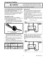
1. Remove control knob and control mounting screws.
2. Work control out of opening far enough to reach the
terminals (on no-defrosting models, it may be
necessary to remove feeler tube cover and straighten
feeler tube enough to allow control to be pulled out
far enough).
3. Look for faulty wiring connections.
4. Check for control points stuck or closed as follows:
If compressor will not run, short across the control
terminals. If compressor starts, control has failed and
must be replaced. If compressor does not start, check
cabinet wiring and compressor components for
failures.
On no defrosting models verify timer is not in the
defrost cycle.
If compressor runs all the time, even though freezer
temperature is below the control cut-out point, make the
following applicable check
On refrigerated shelf models, check control feeler
tube attachment to underside of shelf front for a
positive thermal contact.


