background image

RS1500000 Rev. 0

24

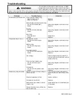
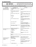
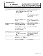
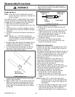
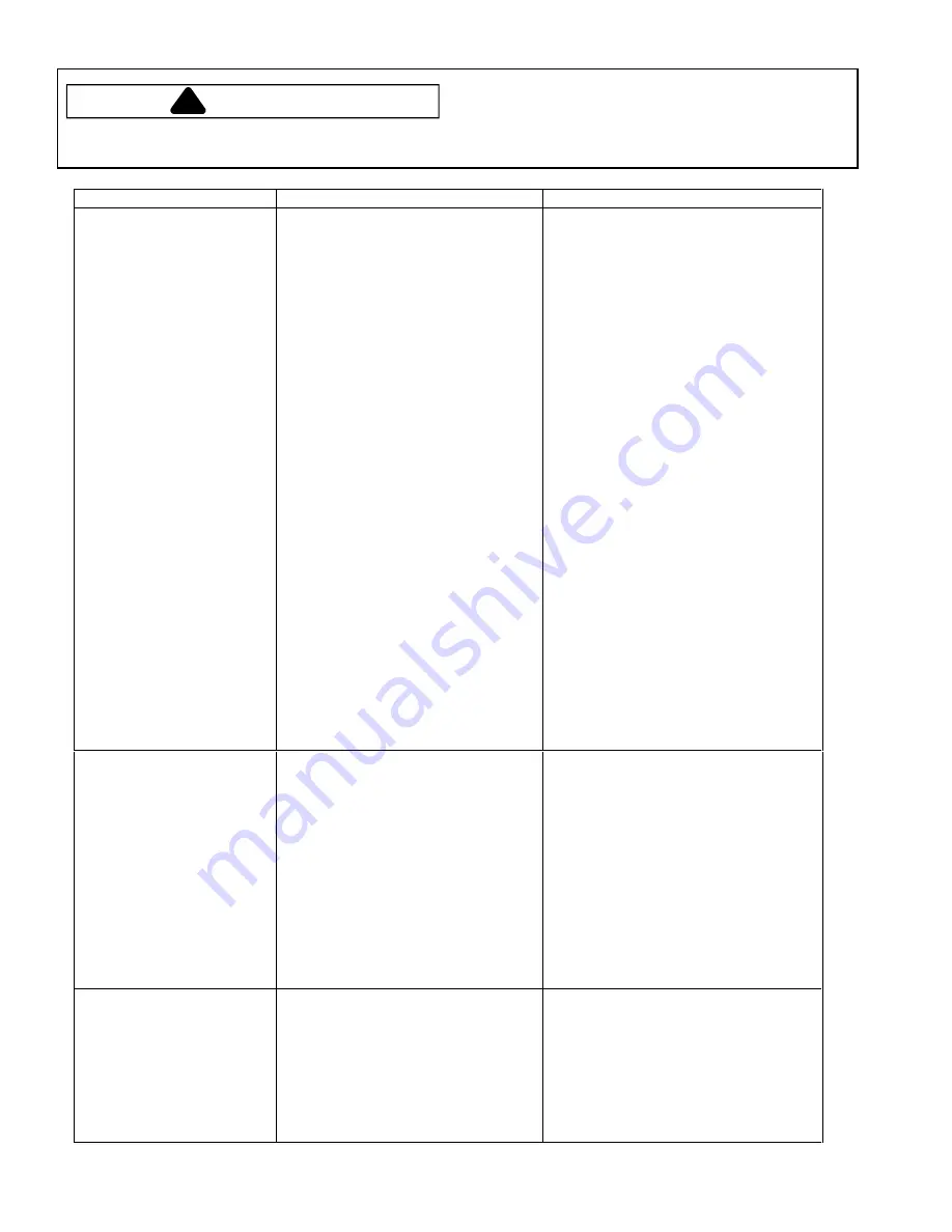
Troubleshooting

To avoid risk electrical shock, personal injury, or death,

always disconnect electrical power source to the freezer

before attempting to service, unless test procedures require

power to be connected. When removing any wiring from terminals they must be replaced on the same terminals.

Ensure all ground wires are connected before certifying unit as repaired and/or operational.

WARNING

!

Problems

Possible Causes

Correction

Compressor runs but
freezer temperature is
higher than


necessary

Temperature control
   Misadjusted or out of calibration
   Failed

Freezer fan motor (no-frost only)
   AC circuit to fan motor open
   Failed

Excessive load of unfrozen food

Door Seal
   Poor seal

   Failed

Loss of sealed system charge

Timer stuck in defrost

Partial restriction

Frost build-up on freezer coil (over
1/2 inch thick (12.7 mm))

Separation of heat exchanger

Adjust control
Replace

See wiring diagram and check circuit
Replace

Advise customer to freeze no more
than 10% of freezer capacity at one
time

Adjust door & gasket as instructed
under improving gasket seal
Replace

Locate and repair leak. Evacuate
undercharge system proper amount
of refrigerant

Replace

Locate and repair restriction.
Evacuate and recharge system with
proper amount of refrigerant

Check door seal. If not Frost Free
model, advise customer to defrost
every time frost builds up to almost 1”
thick (25 mm)

Install heat exchanger repair kit.

Compressor does not run
and no light

No power at AC outlet
   Failed fuse
   Failed outlet

Line cord
   Disconnect
   Failed

Open machine compartment wiring
harness

Two simultaneous problems-light
bulb out and open AC circuit to
compressor

Replace
Advise customer to replace

Plug-in line cord to AC outlet
Replace

See wiring diagram and check circuit

Replace light bulb. See wiring
diagram and check circuit

Sweating but freezer is
working normally
otherwise

Exterior sweating
   Void in insulation

   Overcharged

   Defective door seal

Add insulation inside the affected
area, if possible

Evacuate and recharge system with
right amount of refrigerant. See
specification chart

Replace

Summary of Contents for AU120KW

Page 1: ...P1311101W ESU15JW P1311102W ESU17JW P1311103W ESU20JW P1311104W ESUF15JW P1311105W ESUF17JW P1311106W ESUF20JW P1311107W ESU12JW P1179615W ESU15JW P1179616W ESU17JW P1179617W ESU20JW P1179618W ESUF15...

Page 2: ...operty damage from improper service procedures If performing service on your own product assume responsibility for any personal injury or property damage which may result To locate an authorized servi...

Page 3: ...rmostat No Defrosting Models 20 Freezer Fan No Defrosting Models 21 Testing Freezer Fan Motor 21 Troubleshooting 23 25 Disassembly Procedures Replacing Dryer 26 Replacing Compressor 26 Replacing Heat...

Page 4: ...hand corner of foodliner or on some models exterior back of the outer casing An explanation of coding contained in Type position is shown below ESU F 15 J W Color W White Series H J Storage Capacity 1...

Page 5: ...e Standard Upright Freezer Models Drain plug in bottom front of freezer liner some models Location These recommendations and explanations may help customer receive maximum efficiency from freezer and...

Page 6: ...retainer notch Trim retainer Handle trim End caps Handle Installation Instructions Leveling 1 Install leveling legs under front corners behind toe grille 2 Level freezer side to side and tilt freezer...

Page 7: ...prevent accidents Before Throwing Away Old Freezers Take off the doors Leave the shelves in place to prevent children from easily climbing inside unit Model Identification Read the Owner s Manual tho...

Page 8: ...tween frozen packages in freezer Wait 5 8 hours If freezer temperature is not 0 to 2 F adjust control one number at a time Check again after 5 8 hours Audible Alarm Some models Locate audible alarm on...

Page 9: ...g Guide Wrapping Use moisture vapor proof materials and seal tightly When lids are furnished follow manufacturer s directions for best results Choose materials which are labeled for freezer use Ordina...

Page 10: ...essary 2 Rinse and dry gaskets thoroughly 3 Apply a light film of petroleum jelly on cabinet hinge side to keep gaskets pliable Care and Cleaning Odor Removal 1 Remove all food 2 Wash all interior sur...

Page 11: ...st water 5 Place pans of hot water in freezer 6 Wash all interior surfaces including door floor and walls 7 Replace inside drain plug Drain plug must be properly installed for efficient operation Ligh...

Page 12: ...clock that snaps in and out of the defrost cycle 8 Insulation Foam insulation is very energy efficient and has excellent insulating capabilities However foam insulation is not as sound absorbent as pr...

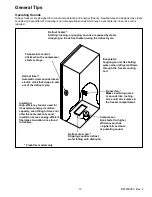
Page 13: ...ling coil Freezer fan Makes a whirring noise or sounds like rushing air as cold air ciculates in the freezer compartment Compressor Runs faster for higher efficiency and has a higher pitched hum or pu...

Page 14: ...l 2 Test point 2 is attached to outlet on the evaporator coil 3 Test point 3 is approximately 6 8 inches from suction port of compressor on the suction line 4 Thermocouple tips should be attached secu...

Page 15: ...ine valve and tubing Access fitting should be prepared as follows Line valve Pressure regulator Gauges Nitrogen Tank and Fittings Suction Process From condensor To condensor Discharge Tube process Com...

Page 16: ...or replacement of a suspected failed component All electrical components are grounded to the cabinet The green center conductor of three wire lead cord is also attached to the cabinet to provide a gr...

Page 17: ...ounds Attach one ohmmeter lead to compressor case Attach second ohmmeter lead to C then S then M terminals on compressor Ohmmeter indicates open on each terminal Capacitor Capacitor can be tested by a...

Page 18: ...flange of the switch and carefully remove Short across the light switch terminals If light operates switch has failed If light fails to operate either the lamp socket or wiring has failed The lamp so...

Page 19: ...b on thermocouple to the freezer shelf near control feeler tube thermal contact point 2 Set control halfway between Off and MAX Cool Close cabinet door and wait for compressor to run through 2 or 3 co...

Page 20: ...collected during the proceeding 12 hour period when operating properly Failure to perform this function will eventually cause an ice build up between the coil fins blockage in air flow and unsatisfac...

Page 21: ...ct ground wire from cover Remove freezer coil cover Before checking fan circuit for failures spin the fan blade to verify nothing has lodged against it which could prevent normal fan operation If blad...

Page 22: ...8 1 1 12 uF 210 V 15 2 Foam 70 90 110 95 115 100 120 105 125 35 45 55 65 90 100 95 115 125 145 165 185 4 2 3 1 3 1 0 9 1 2 0 9 1 2 1 0 1 3 12 uF 210 V 16 9 Foam 70 90 110 105 125 110 130 115 135 40 50...

Page 23: ...Compressor does not run Temperature control AC circuit to control open Failed Starting relay AC circuit to relay open Failed Overload protector AC circuit to overload open Failed Low voltage Timer no...

Page 24: ...ise customer to freeze no more than 10 of freezer capacity at one time Adjust door gasket as instructed under improving gasket seal Replace Locate and repair leak Evacuate undercharge system proper am...

Page 25: ...ent of start time with all other loads on the line Replace Advise customer to freeze no more than 10 of freezer capacity at one time Locate and fix loose connections Compressor runs but does not freez...

Page 26: ...nsertion 9 Cut the inlet tube on the new drier 10 Snap off the scored end of replacement drier with your fingers 11 Install new drier and solder all joints Use silfos on all copper to copper joints On...

Page 27: ...ger tubing to slide tube through entry hole from inside the cabinet 8 Remove clamp retaining the control feeler tube to underside of second shelf counting downward 9 Carefully bend feeler tube down ag...

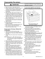
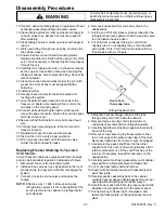
Page 28: ...detach green grounding wire White White Orange Green Red Circulating Fan and Wiring With Coil Cover Removed 8 Remove styrofoam air block from each end of the coil 9 Disconnect defrost heater lead fro...

Page 29: ...s 1 Disconnect line cord from electrical outlet 2 Install service valve as close as possible to the tip of process tube for easy pinch off after recharging the system 3 Connect a hose to service valve...

Page 30: ...e for easy pinch off after recharging the system 3 Connect a hose to service valve and capture the charge NOTE Effective July 1 1992 before opening any refrigeration system it is the responsibility of...

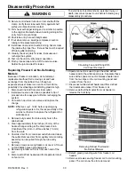
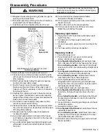
Page 31: ...stat lead and fasten thermostat to freezer coil header 29 Connect green grounding wire to fan motor and to freezer coil cover 30 Test run the unit to verify proper operation 31 Pinch process tube and...

Page 32: ...Thermostat and Mounting Clip Replacing Freezer Fan Motor Remove screws from coil cover and disconnect ground wire from cover Remove freezer coil cover Before checking fan circuit for failures spin the...

Page 33: ...ists of outer door panel bezel and nameplate insert door handle and insert door lock assembly if equipped hinge bushings fiberglass insulation inner door liner door shelf trim and door seal gasket Inn...

Page 34: ...over tighten screws this could crack liner or cause screw head to pull through the hole 3 Always align door Door Handle Door handle and insert are attached to outer door panel by mounting screws whic...

Page 35: ...and close door several times Examine the cabinet flange for transfer of chalk or dampness Failure of the transfer indicates areas of poor seal Improving Gasket Seal In order for gasket to compress eve...

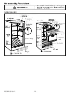
Page 36: ...emperature control plate Temperature control Light switch Cabinet shell Light assembly Cabinet inner liner Cabinet leveller Wire gate Gate brackets Drain tube cap Drain tube and grommet Temperature co...

Page 37: ...s upon the amount of moisture in the system If compressor is operating but evaporator coil or refrigerated shelves are not refrigerated stop the compressor and listen for refrigerant surging through t...

Page 38: ...will not unload and balance with the low side within the prescribed seven to ten minutes after the compressor is stopped High Side low pressure Low Side lower pressure possible vacuum Wattage lower t...

Page 39: ...ise temperature of frozen food Larger unfrozen food loads may also result in longer freezing times 2 Excessive Lid Opening Freezer is not designed to be operated as a refrigerator Length of time and n...

Page 40: ...ly a Voltage under 10 VAC b Voltage over 127 VAC c Lid is being opened frequently so compressor OFF time is too short for pressure equalization d Installation condition is causing compressor to run ho...

Page 41: ...ugh compressor is running continuously food liner temperature will rise 4 Low suction pressures External Or Internal Leak Internal leaks are refrigerant leaks inside foam insulation All other leaks ar...

Page 42: ...om compressor replace oil rather than adding oil Low side leak repairs of HFC134a systems are different from those of CFC 12 systems Ester oils used in HFC134a systems are so hydroscopic that by the t...

Page 43: ...Same Liquid exposure to skin Can cause frostbite Same Vapor exposure to eye Very slight irritant Same Liquid exposure to eye Can cause frostbite Same Above minimum exposure limit Can cause Asphyxiatio...

Page 44: ...e piercing saddle valve Seals must be HFC134a and ester oil compatible Line piercing valves may be used for diagnosis but are not suitable for evacuation or charging due to minute holes pierced in tub...

Page 45: ...ing rails and transfer rubber grommets to replacement compressor 7 Set replacement compressor into position and install retaining clips 8 Remove all rubber plugs Clean stubs of compressor and compare...

Page 46: ...ve 1000 micron level and stabilizes open valve A to vacuum pump and continue evacuating If micron reading rises rapidly and does not stabilize a leak still exists in system Close valve A to vacuum pum...

Page 47: ...ant NOTE Do not use captured or recycled refrigerant in Amana units Captured or recycled refrigerant voids any Amana and or compressor manufacturers warranty Brazing CAUTION Brazing requires high temp...

Page 48: ...he system to a minimum of 75 PSIG by running the compressor for high side testing To pressurise the low side allow entire system to warm up to room temperature If pressure is low enough a leak test wi...

Page 49: ...net liner by utilising special snap nuts clips and other fasteners interior light and switch cold control assembly and cover evaporator coil and cover no frost models shelves and gate mounting hardwar...

Page 50: ...Interior light Light switch 1 Outer case 2 Compressor 3 Control 4 Light plate 5 Fan motor 6 Defrost timer 7 Coil cover Black Black White Green Blue Red Green Red White Green Orange Green Green White D...

Page 51: ...een Red Green Green Capacitor Plug Control Light Light switch Light plate Green Red Black Ground No interior light OPTIONAL Red White Black Control Black Black Black White Red Overload protector Compr...

Page 52: ...itor Plug Defrost thermostat Control Light Light switch Light plate Buzzer Thermostat Slide switch Black Door Switch Lamp White Black Black Black Black Black White White White White White Yellow Green...

Reviews: