RS1500000 Rev. 0
48
Service Information
To avoid risk of electrical shock, personal injury, or death,
always disconnect electrical power source to the freezer
before attempting to service unless test procedures require power to be connected. When removing any wiring from
terminals, replace on the same terminals. Ensure all ground wires are connected before certifying unit as repaired
and/or operational.
WARNING
!
Line Piercing Valves
Line piercing valves may be used for diagnosis, but are
not suitable for evacuating or charging due to the minute
holes pierced in the tubing.
WARNING
!
Line piercing valve should not be left on the system,
connection to tubing is not hermetically sealed and
eventually a leak will occur.
Upright freezers which are insulated with foamed-in
polyurethane foam have their condenser tubing
embedded in this foamed insulation within the cabinet
wall. Liner cannot be removed and there is no access to
the tubing to removed, repaired, or replaced.
NOTE:
Polyurethane insulation contains refrigerant
R11/R141B/R22. Care must be taken when
testing. Isolate the area as much as possible so
that the leak detector will not falsely indicate a
leak of R11/R141B/R22 vapor.
If there is an undercharge of refrigerant and the system
has not been recently opened, there is probably a leak in
the system. First locate and repair the leak. evacuated
and recharged with the proper amount of refrigerant.
Replaced the dryer whenever a new charge of refrigerant
is added.
NOTE:
Effective July 1, 1992, before opening any
refrigeration system it is the responsibility of the
service technician to capture the refrigerant for
safe disposal.
Presence of oil around a tubing joint usually indicates a
leak. Always use a leak detector to determine if the joint
is leaking.
Pressurise the system to a minimum of 75 PSIG, by
running the compressor for high side testing. To
pressurise the low side, allow entire system to warm up
to room temperature.
If pressure is low enough a leak test will be impossible to
perform. Install a service valve to compressor process
tube and check pressure. Recover remaining
refrigerant. Separate and pressurise high & low side
independently, allowing unit to settle.Check gauges for
pressure drop.
Leak detector can insolate larger leaks and generally
locate small ones, but to actually pinpoint extremely
small leaks in the high side, soap bubble solution will
need to be performed.
NOTE:
Use soap bubble solution only when the system
has a positive pressure. Using it where a
vacuum is present could pull moisture or soap
bubbles into the system.
Brush liquid detergent over testing area and watch for
bubbles. This may take a few minutes for a bubble to
appear if leaks are extermely small.
After replacing a component always evacuate, add
refrigerant, and test for leaks on all joints before
recharging. Clean excess soldering flux from new joints
before testing to prevent pinhole leaks at a later time.
Altitude Adjustment
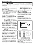
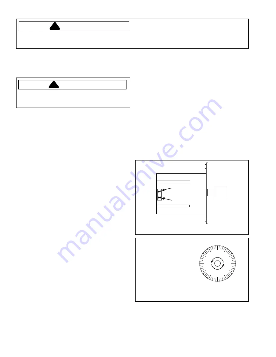
All models covered in this manual are equipped with a
Cutler Hammer temperature control. It has two
adjustment screws, both of which must be turned to
compensate for variance in altitude. Screw turns are very
critical, use circular scale as a guide.
Cut-out screw
Cut-in screw
Temperature Control
00
50
45
40
35
30
25
20
15
10
05
55
Alititude
in feet
Counter Clockwise
turns
2,000
3,000
4,000
5,000
6,000
7,000
8,000
9,000
10,000
7 / 60
13 / 60
19 / 60
25 / 60
31 / 60
37 / 60
43 / 60
49 / 60
55 / 60
Altitude Correction Both Cut-In and
Cut-Out Screws Must Be Adjusted
This scale may be used as a guide for measuring
degrees of rotation required for altitude correction. The
arrows indicate direction of screw rotation 1/60 of a turn
equals 6° of rotation.
Turn cut-in or cut-out screws clockwise to obtain colder
operating temperatures.

