RS1500000 Rev. 1
50
To avoid risk of electrical shock, personal injury, or death, disconnect power to freezer before servicing, unless
testing requires it. Wires removed during disassembly must be replaced on proper terminals to insure correct
grounding and polarization.
CAUTION
!
High Voltage
!
WARNING
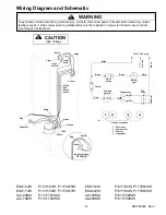
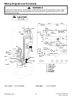
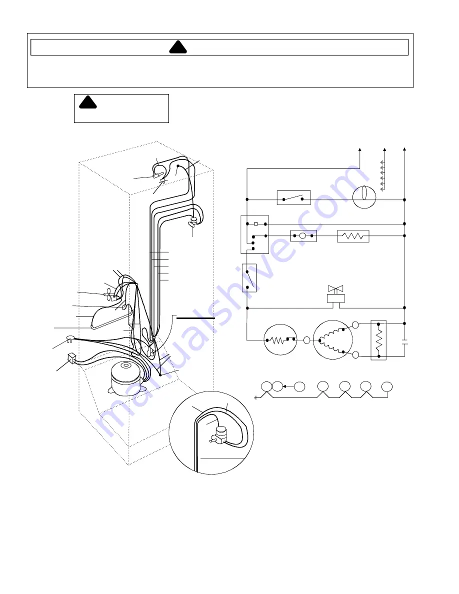
Wiring Diagram and Schematic
1
2
7
3
4
5
6
Overload
protector
Compressor
Freezer
fan
Control
Defrost
timer
Defrost
thermostat
Defrost
heater
Interior
light
Light
switch
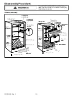
1 - Outer case
2 - Compressor
3 - Control
4 - Light plate
5 - Fan motor
6 - Defrost timer
7 - Coil cover
Black
Black
White
Green
Blue
Red
Green
Red
White
Green
Orange
Green
Green
White
Defrost timer
Blue T4
White T3
Yellow T2
Black T1
Heater
Fan
Capacitor
Plug
Defrost
thermostat
Control
Light
Light
switch
Light
plate
Green
Red
Blue
Black
Black
Yellow
Black
Black
White
White
Red
Red
Wh
it
e
Black
Blue
G
round
Ground
No interior light
OPTIONAL
To 115 VAC plug
PTC
relay
R
S
C
Ca
p
a
ci
to
r
White
1
3
2
4
Ground schematic
ESUF15JW
P1311105W, P1179619W
ESUF17JW
P1311106W, P1179620W
ESUF20JW
P1311107W, P1179621W
AUF150KW
P1317705W

