16
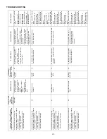
HTR k W
9
10
11
AVPTC24B14A AVPTC30C14A
AVPTC36C14A AVPTC48C14A
AVPTC42D14A†
AVPTC48D14A†† AVPTC60D14A†††
3
ON
ON
ON
550
600
NR
NR
850**
NR
NR
5
ON
ON
OFF
650
700
850
850
1250
1250
1250
6
ON
OFF
ON
700
750
900
900
1300
1300
1300
8
ON
OFF
OFF
800
875
1000
1000
1500
1500
1500
10
OFF
ON
ON
850
950
1200
1200
1550
1550
1550
15
OFF
ON
OFF
NR
NR
1440
1440
1720
1720
1780
19*
NR
NR
1500
1500
NR
NR
NR
20
NR
NR
1500
1500
1800
1815
1850
21 or 25*
OFF
OFF
OFF
NR
NR
NR
NR
NR
1850
1850
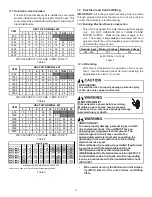
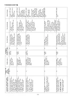
ELECTRIC HEAT AIRFLOW TABLE
OFF
OFF
ON
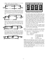
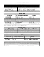
B ------- 30 sec/50% 60 sec/100%
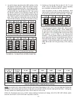
Speed Selection Dip Switches
A OFF OFF OFF OFF OFF OFF
TAP S1 S2 S3 S4 S5 S6
B ON OFF ON OFF ON OFF
A ------- -------- 60 sec/100%
To
set Airflow:
(1) Select model and desired High Stage Cooling
Airflow. Determine the corresponding tap (A, B, C, D). Set dip
switches S1 and S2 to the appropriate ON / OFF positions.
(2) Select model and installed electric heater size. Set dip
switches S9, S10, and S11 to the appropriate ON / OFF positions.
(3) If airflow adjustment is required set Trim Enable Switch
to
S8
ON (OFF = 0% Trim) and set S3 and S4 to appropriate ON / OFF
positions. Tap A is +5%,Tap B is -5%, Tap C is +10%, Tap D is
-10%.
D ON ON ON ON ON ON
Cool Adjust Profile
Selection Selection Selection
Switches Switches Switches
Notes:
1. Airflow data shown applies to legacy mode operation only.
For a fully communicating system, please see the outdoor
unit's installation instructions for cooling and heat pump
airflow data. See
ComfortNet System-Airflow Consideration
section for details.
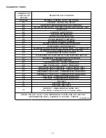
2. Airflow blink codes are approximations of actual airflow.
Profiles Pre-Run Short-Run OFF Delay
C OFF ON OFF ON OFF ON
C ------- 7.5 min/82% 60 sec/100%
D 30 sec/50% 7.5 min/82% 30 sec/50%
To
Set Comfort
mode:
Select desired Comfort Mode Profile (see
profiles above). Set dip switches S5 and S6 to appropriate ON /
OFF positions.
Dehumidification:
To enable, set dip switch S7 to ON. Cooling
airflow will be reduced to 85% of nominal value during cool call
when Dehum command is present. To disable, set S7 to OFF.
Continuous
Fan
Speed:
Use dip switches S12 and S13 to select
one of 4 continuous fan speeds, Tap A is 25%. Tap B is 50%, Tap
C is 75%, Tap D is 100%.
Continuous
Fan
Speed
S12
S13
OFF
ON
OFF
ON
OFF
OFF
ON
ON
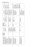
Model
Speed tap
Low stage
(CFM)
High stage
(CFM)
A
410
610
B
565
835
C
660
970
D
765
1125
A
440
610
B
605
835
C
740
1020
D
885
1225
A
500
725
B
700
1000
C
930
1330
D
1120
1600
A
500
725
B
700
1000
C
930
1330
D
1120
1600
A
560
800
B
763
1090
C
994
1420
D
1225
1750
A
900
1350
B
1035
1550
C
1140
1700
D
1200
1800
A
1210
1610
B
1365
1815
C
1450
1920
D
1525
2025
AVPTC60D14**
Cooling/Heat Pump Airflow Table
AVPTC24B14**
AVPTC30C14**
AVPTC36C14**
AVPTC42D14**
AVPTC48D14**
AVPTC48C14**
NOTE:
Airflow blink codes are approximations of actual airflow. Airflows
provided are at 0.3 static.
Note: Airflow data shown applies to the electric heat only in either legacy mode or communicating mode operationNR - Not rated* Within thermostat
user menu, CTK0* communicating thermostat will display 20 kW for OFF-OFF-ON dip switch selection and 21 kW for OFF-OFF-OFF dip switch
selection.
† For match up with a 2 ton outdoor unit: Heater kit application shall not exceed 10 kW. Airflow for 5 kW up to 10 kW heater kits shall be set to 850 cfm speed tap of
ON-ON-ON.
†† For match up with a 3 ton outdoor unit: Heater kit application shall not exceed 15 kW.
Airflow for 5 kW up to 15 kW heater kits shall be set to 1300 cfm speed tap of ON-OFF-ON.
††† For match up with a 3.5 ton outdoor unit: Heater kit application shall not exceed 20 kW.
Airflow for 5 kW up to 20 kW heater kits shall be set to 1500 cfm speed tap of ON-OFF-OFF
** 3 kW heater kit is not applicable for this indoor application.

