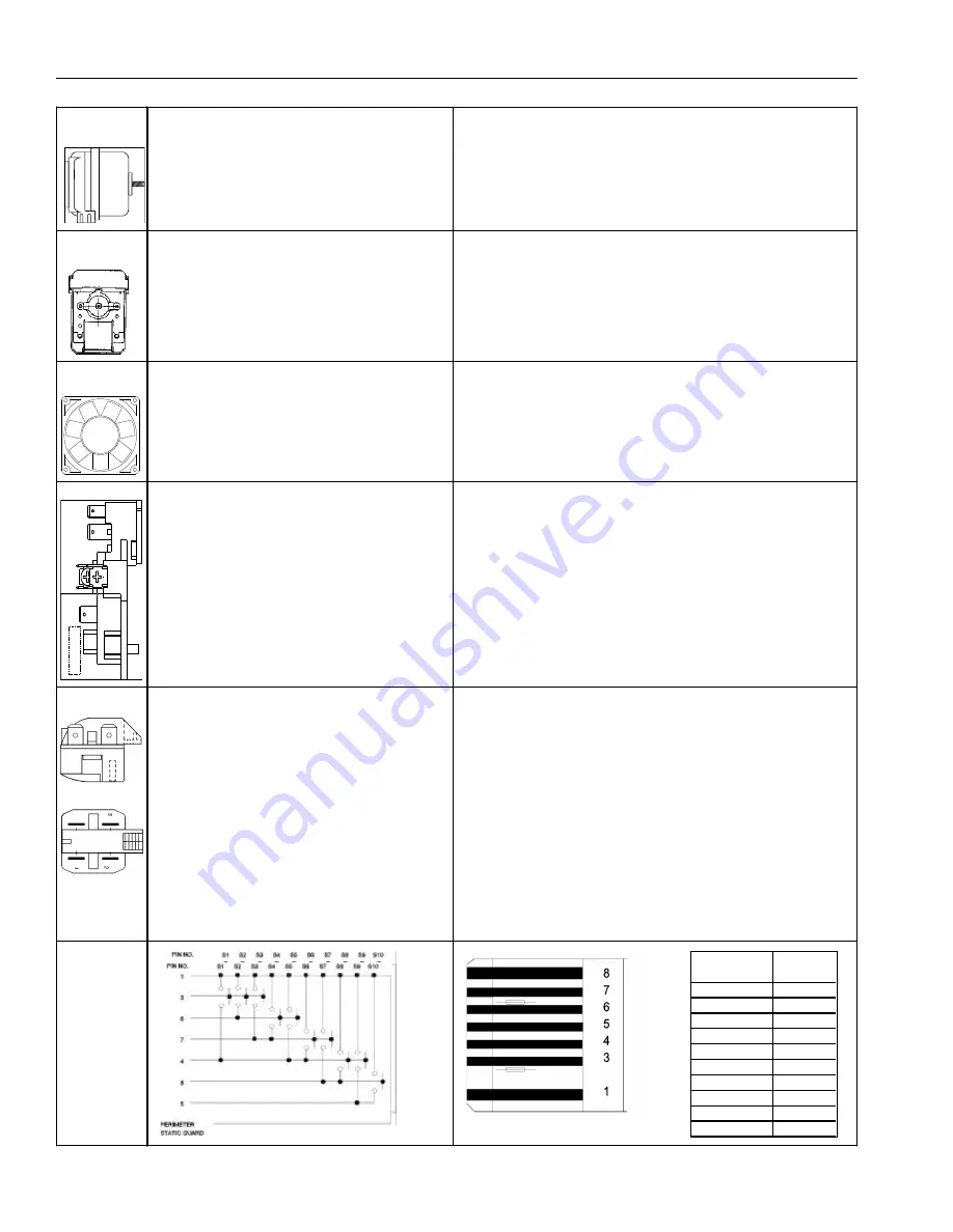
Component Function and Testing
RS1200001 Rev. 1
22
April 1998
Motor,
condenser psc
Condenser fan moves cooling air across condenser coil
and compressor body.
The condenser motor is in a parallel circuit w ith the
compressor.
Check resistance across coil.
Motor, ecm
evaporator fan
Motor,
refrigerator fan
Refrigerator fan circulates cold air into refrigerator
compartment.
The refrigerator fan motor is in a series circuit w ith the
semi conductor sw itch.
See "Refrigeration and Defrost Component Checks Made at High Voltage
Board" section for D.C. voltage check at high voltage board. Check for
voltage at motor also.
Overload
Relay, PTC
With pow er off check resistance.
Across terminals 2 & 3:
Normal = 3 to 12 ohms
Shorted = 0 ohms
Open = infinite ohms
Sw itch,
keyboard
Overload is a temperature and current sensing type.
Overload opens w hen sensing a high current or high
compressor temperature.
After overload opens, overload can require up to 2
hours to reset, depending on ambient temperature and
residual heat load in compressor.
1. Disconnect pow er to refrigerator.
2. Remove relay cover and pull relay off compressor.
3. Pull overload protector off compressor common terminal.
3. With ohmmeter, check resistance betw een 1/4 " male terminal and
female pin receptacle terminal w hich pushes onto compressor common
terminal. At ambient temperature, overload protector should have less
than 1 ohm resistance. An open overload protector w ill have infinite
resistance.
When voltage is connected and PTC is cooled, current
passes through PTC to the start w inding.
After a short time, current w ill have heated the resistor
in PTC and resistance w ill rise. This blocks current
flow through PTC.
Start w inding remains in the circuit through the run
capacitor.
Solid state relay plugs directly on compressor start and
run terminals. Relay terminals 2 and 3 are connected
w ithin relay. Run capacitor is connected to relay
terminal 3. The L2 side of 120 VAC pow er is
connected to relay terminal 2.
Evaporator motor moves air across evaporator
coil and throughout refrigerator.
Evaporator fan motor is in a parallel circuit w ith
compressor, w ith a delay for w arm coil
conditions.
Check resistance from ground connector solder. Trace to motor frame
must not exceed .05 ohms. Check pow er at connector to evaporator
motor.
Switch
Functions
Continuity
Test
Display On
1 and 3
Freezer Temp
3 and 6
Ref Temp
3 and 7
Warmer
6 and 7
Colder
4 and 6
Vacation
4 and 7
Max Ref
7 and 8
Max Frz
4 and 8
Alarm Off
4 and 5
Display Off
5 and 8
Summary of Contents for Bottom Freezer Refrigerator
Page 17: ...November 1996 17 RS1200001 Refrigerant Flow ...
Page 18: ...RS1200001 18 November 1996 Air Flow ...
Page 19: ...November 1996 19 RS1200001 Machine Compartment Assembly ...
Page 25: ...November 1996 25 RS1200001 Electronic Functional Description ...
Page 50: ...RS1200001 50 November1996 Ice Maker Wiring Diagram and Parts Layout 115 ...


