RS1200001
6
November 1996
Installation Instructions
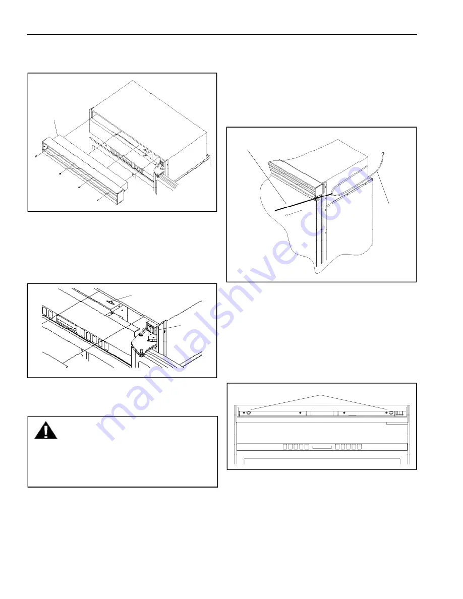
8. Remove (4) 1/4" screws with a magnetic extended
screw driver.
9. Pull air grille assembly forward.
10. Verify operation by plugging in power cord. Power
switch will be shipped in the
on
position and the
showroom switch will be shipped in
the off
position.
Display should flash. Press any key. There is a 6
minute delay before refrigerator starts. Verify
position of each switch if there is no power to
refrigerator.
11. Pull end of nylon cord around refrigerator side (side
without 1/4" panel installed, if any) level with top of
refrigerator door. Tape cord in place.
WARNING
To avoid electrical shock which can cause
severe personal injury or death, disconnect
power to refrigerator using power switch
before performing any installation procedure.
After performing installation procedure,
connect power using power switch.
Air grille
assembly
1/4" screws
Showroom
switch
Power
switch
12. Roll refrigerator into cutout to within 3" of being
flush with kitchen cabinets. To avoid kitchen cabinet
damage, place cardboard between kitchen cabinets
and refrigerator. Push cardboard back with
refrigerator and remove cardboard when refrigerator
is in place. Remove power cord slack by pulling
nylon cord straight out while pushing refrigerator
completely into place. Power and nylon cord will
rest along refrigerator side.
13. Level refrigerator by turning front and rear leveling
wheel bolts clockwise to raise refrigerator and
counterclockwise to lower refrigerator. Rotate
stabilizing legs until firmly in place against floor.
14. Align refrigerator with sides of kitchen cabinets
using leveling bolts.
15. Secure lag bolts by removing center air grille blade.
Screw lag bolts securely into 2x4 mounting board
using a magnetic 6" extension socket. See
"Installation Specifications".
16. Push extra nylon cord back in along side of
refrigerator out of sight or cord can be flush with
refrigerator.
Pull nylon
cord straight
out
Lag bolts
Power cord
must rest
as shown
Summary of Contents for Bottom Freezer Refrigerator
Page 17: ...November 1996 17 RS1200001 Refrigerant Flow ...
Page 18: ...RS1200001 18 November 1996 Air Flow ...
Page 19: ...November 1996 19 RS1200001 Machine Compartment Assembly ...
Page 25: ...November 1996 25 RS1200001 Electronic Functional Description ...
Page 50: ...RS1200001 50 November1996 Ice Maker Wiring Diagram and Parts Layout 115 ...


