SERVICING
63
Rev. 0
2. Next, remove wire connections from gas valve termi-
nals.
3. Using an ohmmeter, test across the gas valve coil ter-
minals M1 and C2.
Note: Make sure gas valve switch is in the "ON" position
when taking reading.
4. Should read approximately 100 Ohms for the White-
Rodgers 36E22 gas valve.
If not as above, replace the entire gas valve.
5. After check and/or replacement of gas valve, turn on
gas to furnace and check for leaks. If leaks are found,
repair and then reinstall burner compartment door.
6. Turn on electrical power and verify proper unit opera-
tion.
S-10 CHECKING MAIN BURNERS
The main burners are used to provide complete combus-
tion of various fuels in a limited space, and transfer this
heat of the burning process to the heat exchanger.
Proper ignition, combustion, and extinction are primarily due
to burner design, orifice sizing, gas pressure, primary and
secondary air, vent and proper seating of burners.
WARNING
Disconnect Electrical Power and Shut Off Gas Supply:
1. Remove burner compartment door to gain access to
manifold assembly.
2. Remove the entire manifold assembly from the front of
the heat exchanger assembly.
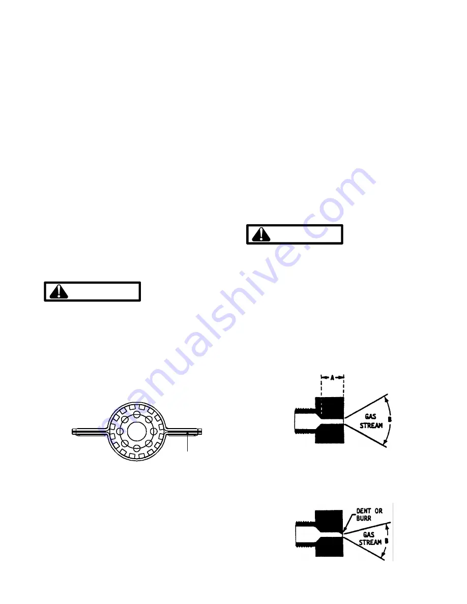
3. Check main burners for signs of rust, oversized and
undersized carryover ports or restrictions of foreign ma-
terial, etc. Refer to the following figure for the proper
dimension of the carryover ports.
SLOT TO BE
.023" - .027"
GUCA / GCCA Beckett Burner
4. After completing check, repair and/or replacement of
main burners, reinstall manifold assembly to front of
heat exchanger.
5. Turn on gas to furnace and check for leaks. If leaks are
found, repair and then reinstall burner compartment
door.
6. Turn on electrical power and verify poper unit opera-
tion.
S-11 CHECKING ORIFICES
A predetermined fixed gas orifice is used in all of these
furnaces. That is an orifice which has a fixed bore and po-
sition.
No resizing should be attempted until all factors are taken
into consideration such as inlet manifold gas pressure, align-
ment, positioning, specific gravity and BTU content of the
gas being consumed.
The only time resizing is required is when a reduction in
firing rate is required for an increase in altitude.
Orifices should be treated with care in order to prevent dam-
age. They should be removed and installed with a box-end
wrench in order to prevent distortion. In no instance should
an orifice be peened over and redrilled. This will change
the angle or deflection of the vacuum effect or entraining of
primary air, which will make it difficult to adjust the flame
properly. This same problem can occur if an orifice spud of
a different length is substituted.
WARNING
Disconnect Electrical Power and Shut Off Gas Supply:
1. Remove top access door to gain access to the mani-
fold assembly.
2. Remove manifold from burner bracket.
3. Check orifice visually for distortion and/or burrs.
4. Check orifice size with orifice sizing drills.
Note: It may be necessary to remove orifices from mani-
fold to view more clearly.
5. If resizing is required, a new orifice of the same physi-
cal size and angle with proper drill size opening should
be installed.
The length of Dimension "A" determines included angle of
Spray "B".
A dent of burr will cause severe deflection of gas stream.


